


P
ower
problems
P
ower
symptom
S
u
gg
ested
action
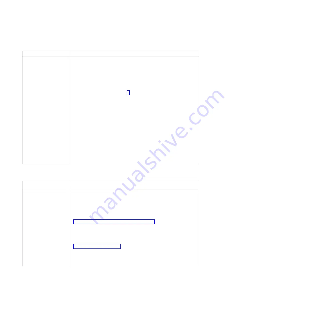
The
blade
server
does
not
turn
on.
1
.
Make
sure
that:
a.
The
power-on
L
E
D
on
the
front
of
the
BladeCenter
unit
is
lit.
b.
The
L
E
Ds
on
all
the
BladeCenter
power
modules
are
lit.
c.
If
the
blade
server
is
in
blade
bays
7
through
1
4,
power
modules
are
in
power-module
bays
1
,
2,
3
,
and
4.
d.
The
power-on
L
E
D
on
the
blade-server
control
panel
is
flashing
slowly.
v
If
the
power-on
L
E
D
is
flashing
rapidly
and
continues
to
do
so,
the
blade
server
is
not
communicating
with
the
Management
Module
;
reseat
the
blade
server
and
go
to
step
v
If
the
power
L
E
D
is
off,
either
the
blade
bay
is
not
receiving
power,
the
blade
server
is
defective,
or
the
L
E
D
information
panel
is
loose
or
defective.
e.
Local
power
control
for
the
blade
server
is
enabled
(
use
the
BladeCenter
Management
Module
Web
interface
to
make
sure
)
,
or
the
blade
server
was
instructed
through
the
Management
Module
(
Web
interface
)
to
turn
on.
f.
The
blade
server
is
not
installed
in
blade
bay
6/7,
because
if
a
blade
server
is
installed
in
either
of
these
bays,
it
can
cause
damage
to
the
power
supply.
A
blade
server
can
be
installed
in
blade
bays
5
/6
or
7/
8
,
but
not
in
6/7.
2.
If
you
j
ust
installed
an
option
in
the
blade
server,
remove
it,
and
restart
the
blade
server.
If
the
blade
server
now
turns
on,
troubleshoot
the
option
(
see
the
documentation
that
comes
with
the
option
for
information
)
.
3
.
Try
another
blade
server
in
the
blade
bay
;
if
it
works,
replace
the
faulty
blade
server.
4.
If
the
problem
remains,
BladeCenter
QS20
Problem
Determination
and
Service
Guide
.
N
etwor
k
connection
problems
N
etwor
k
connection
symptom
S
u
gg
ested
action
O
ne
or
more
blade
servers
are
unable
to
communicate
with
the
network.
Make
sure
that:
v
The
switch
modules
for
the
network
interface
being
used
are
installed
in
the
correct
BladeCenter
bays
and
are
configured
and
operating
correctly.
v
The
settings
in
the
switch
module
are
correct
for
the
blade
server
(
settings
in
the
switch
module
are
blade
server
specific
)
.
For
additional
information,
see:
v
v
The
following
documentation:
–
IBM
BladeCenter
(Type
8677)
Hardware
Maintenance
Manual
and
Troubleshooting
Guide
N
ote:
For
the
latest
editions
of
the
IBM
BladeCenter
documentation,
go
to
http://www.ibm.com/pc/support/
on
the
World
Wide
Web.
v
O
ther
product-specific
documentation
that
comes
with
the
switch
module
If
the
problem
remains,
see
the
BladeCenter
QS20
Problem
Determination
and
Service
Guide
.
56
BladeCenter
QS20
Type
0200:
Installation
and
User
’
s
Guide
Summary of Contents for BladeCenter QS20
Page 3: ...BladeCenter QS20 Type 0200 Installation and User s Guide SC33 8284 02...
Page 28: ...14 BladeCenter QS20 Type 0200 Installation and User s Guide...
Page 34: ...20 BladeCenter QS20 Type 0200 Installation and User s Guide...
Page 58: ...44 BladeCenter QS20 Type 0200 Installation and User s Guide...
Page 66: ...52 BladeCenter QS20 Type 0200 Installation and User s Guide...
Page 86: ...72 BladeCenter QS20 Type 0200 Installation and User s Guide...
Page 90: ...76 BladeCenter QS20 Type 0200 Installation and User s Guide...
Page 91: ......
Page 92: ...Part Number 43W7874 Printed in USA SC33 8284 02 1P P N 43W7874...


