4.
If an optional expansion unit is installed, remove the expansion unit (see
“Removing an optional expansion unit” on page 57).
5.
Locate the microprocessor that will be removed (see “Blade server connectors”
on page 14).
6.
If you are removing microprocessor 2, remove the bezel (see “Removing the
bezel assembly” on page 59).
7.
Before removing the microprocessor, you must remove the memory module
closest to the microprocessor.
a.
If you are removing microprocessor 1, remove the memory module from
DIMM connector 1 (see “Removing a memory module” on page 63).
b.
If you are removing microprocessor 2, remove the memory module from
DIMM connector 10 (see “Removing a memory module” on page 63).
8.
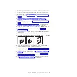
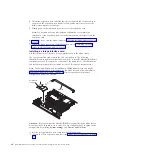
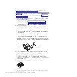
Remove the heat sink.
Attention:
Do not touch the thermal material on the bottom of the heat sink.
Touching the thermal material will contaminate it. If the thermal material on
the microprocessor or heat sink becomes contaminated, you must replace the
heat sink.
a.
Loosen the screw on one side of the heat sink to break the seal with the
microprocessor.
b.
Use a screwdriver to loosen the screws on the heat sink, rotating each
screw two full turns until each screw is loose.
c.
Use your fingers to gently pull the heat sink from the microprocessor.
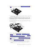
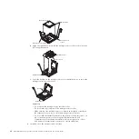
Attention:
Do not use any tools or sharp objects to lift the release lever on
the microprocessor socket. Doing so might result in permanent damage to the
system board.
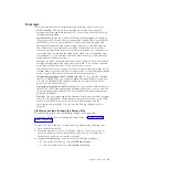
Microprocessor
release lever
Microprocessor
retainer
9.
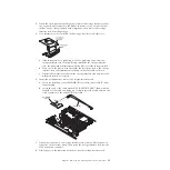
Rotate the locking lever on the microprocessor socket from its closed and
locked position until it stops in the fully open position (approximately a 135°
angle). Lift the microprocessor retainer cover upward.
Attention:
Do not touch the microprocessor contacts; handle the
microprocessor by the edges only. Contaminants on the microprocessor
contacts, such as oil from your skin, can cause connection failures between the
contacts and the socket.
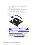
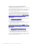
10.
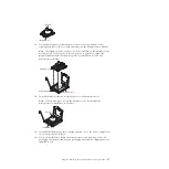
Find the microprocessor installation tool that came with the new
microprocessor.
Installation tool
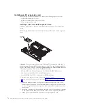
11.
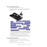
Twist the handle on the microprocessor tool counterclockwise so that it is in
the open position.
86
BladeCenter HS22V Type 7871 and 1949: Problem Determination and Service Guide
Summary of Contents for BladeCenter HS22V 7871
Page 1: ...BladeCenter HS22V Type 7871 and 1949 Problem Determination and Service Guide...
Page 2: ......
Page 3: ...BladeCenter HS22V Type 7871 and 1949 Problem Determination and Service Guide...
Page 16: ...xiv BladeCenter HS22V Type 7871 and 1949 Problem Determination and Service Guide...
Page 20: ...4 BladeCenter HS22V Type 7871 and 1949 Problem Determination and Service Guide...
Page 34: ...18 BladeCenter HS22V Type 7871 and 1949 Problem Determination and Service Guide...
Page 64: ...48 BladeCenter HS22V Type 7871 and 1949 Problem Determination and Service Guide...
Page 112: ...96 BladeCenter HS22V Type 7871 and 1949 Problem Determination and Service Guide...
Page 240: ...224 BladeCenter HS22V Type 7871 and 1949 Problem Determination and Service Guide...
Page 244: ...228 BladeCenter HS22V Type 7871 and 1949 Problem Determination and Service Guide...
Page 252: ...236 BladeCenter HS22V Type 7871 and 1949 Problem Determination and Service Guide...
Page 257: ......
Page 258: ...Part Number 00Y8038 Printed in USA 1P P N 00Y8038...


