background image


 v


Contents

Safety Information . . . . . . . . . . . . . . . . . .   vii

Lithium battery notice  . . . . . . . . . . . . . . . . . . . . . . . . . .   viii
Modem safety information  . . . . . . . . . . . . . . . . . . . . . .   viii
Laser compliance statement. . . . . . . . . . . . . . . . . . . . . . . .  ix

About this book . . . . . . . . . . . . . . . . . . . . .  xi

How this book is organized . . . . . . . . . . . . . . . . . . . . . . . .  xi
Information resources . . . . . . . . . . . . . . . . . . . . . . . . . . . .  xii

Chapter 1. Overview  . . . . . . . . . . . . . . . . . . 1

Identifying your computer. . . . . . . . . . . . . . . . . . . . . . . . .   1
Features. . . . . . . . . . . . . . . . . . . . . . . . . . . . . . . . . . . . . . . . .   2
Specifications . . . . . . . . . . . . . . . . . . . . . . . . . . . . . . . . . . . .   4
Available options . . . . . . . . . . . . . . . . . . . . . . . . . . . . . . . . .   6
Tools required  . . . . . . . . . . . . . . . . . . . . . . . . . . . . . . . . . . .   6
Handling static-sensitive devices . . . . . . . . . . . . . . . . . . .   6

Chapter 2. Installing external options . . . . 9

Locating the connectors on the front of your computer    9
Locating the connectors on the rear of your computer   10

High-performance video adapter  . . . . . . . . . . . . . . .   11
High-performance audio adapter . . . . . . . . . . . . . . .   12
Modem. . . . . . . . . . . . . . . . . . . . . . . . . . . . . . . . . . . . . .   13
Network adapter  . . . . . . . . . . . . . . . . . . . . . . . . . . . . .   13

Obtaining device drivers . . . . . . . . . . . . . . . . . . . . . . . . .   14

Chapter 3. Installing internal options  . . . 15

Removing the cover  . . . . . . . . . . . . . . . . . . . . . . . . . . . . .   15

Removing the power supply . . . . . . . . . . . . . . . . . . . . . .   15
Locating components  . . . . . . . . . . . . . . . . . . . . . . . . . . . .   17
Installing options on the system board  . . . . . . . . . . . . .  17

Accessing the system board . . . . . . . . . . . . . . . . . . . .   17
Identifying parts on the system board  . . . . . . . . . . .   18
Installing memory  . . . . . . . . . . . . . . . . . . . . . . . . . . . .   19
Installing adapters . . . . . . . . . . . . . . . . . . . . . . . . . . . .   21

Installing internal drives. . . . . . . . . . . . . . . . . . . . . . . . . .   22

Drive specifications . . . . . . . . . . . . . . . . . . . . . . . . . . .   23
Power and signal cables for internal drives . . . . . . .   24
Installing internal drives in bays 1, and 2. . . . . . . . .   25
Installing internal drives in bay 4  . . . . . . . . . . . . . . .   27

Replacing the power supply  . . . . . . . . . . . . . . . . . . . . . .   29
Replacing the cover and connecting the cables. . . . . . .   30

Chapter 4. Updating the computer 

configuration . . . . . . . . . . . . . . . . . . . . . . 33

Verifying that an option is installed correctly . . . . . . . .   33
Configuring PCI adapters  . . . . . . . . . . . . . . . . . . . . . . . .   34
Configuring startup devices  . . . . . . . . . . . . . . . . . . . . . .   34
Erasing a lost or forgotten password (clearing CMOS)  34

Appendix A. Changing the battery. . . . . . 37

Appendix B. Updating System Programs 39

Appendix C. Notices and trademarks  . . . 41

Summary of Contents for A60 Type 6833

Page 1: ...IBM NetVista User Guide A60 Type 6833 A60i Type 6832...

Page 2: ......

Page 3: ...IBM NetVista User Guide A60 Type 6833 A60i Type 6832...

Page 4: ...on page vii and Appendix C Notices and trademarks on page 41 Note First Edition February 2001 Copyright International Business Machines Corporation 2001 All rights reserved US Government Users Restri...

Page 5: ...g internal options 15 Removing the cover 15 Removing the power supply 15 Locating components 17 Installing options on the system board 17 Accessing the system board 17 Identifying parts on the system...

Page 6: ...vi User Guide...

Page 7: ...lectrique provenant de l alimentation du t l phone et des c bles de transmission peut pr senter un danger Pour viter tout risque de choc lectrique Ne manipulez aucun c ble et n effectuez aucune op ra...

Page 8: ...remplacement incorrect de la batterie Remplacer uniquement par une batterie IBM de type ou d un type quivalent recommand par le fabricant La batterie contient du lithium et peut exploser en cas de mau...

Page 9: ...ez toujours un t l phone sans fil En cas de fuite de gaz n utilisez jamais un t l phone situ proximit de la fuite Laser compliance statement Some IBM Personal Computer models are equipped from the fac...

Page 10: ...emarques suivantes ATTENTION Pour viter tout risque d exposition au rayon laser respectez les consignes de r glage et d utilisation des commandes ainsi que les proc dures d crites L ouverture de l uni...

Page 11: ...ion to orient you to the connectors on your computer and instructions for installing external options and peripheral devices Chapter 3 Installing internal options provides instructions for removing th...

Page 12: ...mation about your computer If you have Internet access the most up to date manuals for your computer are available from the World Wide Web To access this information point your browser to http www ibm...

Page 13: ...mation about the use operation and maintenance of your computer Access IBM also contains information to help you solve problems and get repair service or other technical assistance Identifying your co...

Page 14: ...sk drive EIDE CD drive DVD drive some models CD RW drive some models or DVD CDRW drive some models Video controller High performance accelerated graphics port AGP adapter Audio subsystem 16 bit integr...

Page 15: ...control Startup without diskette drive keyboard or mouse Unattended start mode Diskette and hard disk I O control Serial and parallel port I O control Security profile by device IBM preinstalled softw...

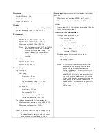
Page 16: ...Specifications This section lists the physical specifications for the NetVista computer Your computer has three 32 bit PCI expansion slots one AGP slot and four drive bays Note The computer is classi...

Page 17: ...ption and heat output vary depending on the number and type of optional features installed and the power management optional features in use Heat output approximate in British thermal units Btu per ho...

Page 18: ...pc support Tools required To install some options in your computer you might need a flat blade screwdriver Additional tools might be needed for certain options See the instructions that come with the...

Page 19: ...ssible remove the option and install it directly in the computer without setting the option down When this is not possible place the static protective package that the option came in on a smooth level...

Page 20: ...8 User Guide...

Page 21: ...n in this chapter to identify the required connector and then use the instructions that come with the option to help you make the connection and install any software or device drivers that are require...

Page 22: ...where to connect the cables on your computer 1 Power connector 8 Audio line in connector 2 Mouse connector 9 Audio line out connector 3 Keyboard connector 10 Microphone connector 4 USB connector 11 Ga...

Page 23: ...o device such as a stereo system When you attach an external audio device a cable is connected between the audio line out connector of the device and the audio line in connector of the computer Audio...

Page 24: ...anagement Signaling DPMS standard 2 S Video connector out Used to attach a television set that has an S Video connector The S Video cable required to connect the television set to the adapter is a sep...

Page 25: ...ctor 2 Used to send audio signals from the computer to external devices such as powered stereo speakers speakers with built in amplifiers headphones multimedia keyboards or the audio line in connector...

Page 26: ...ice drivers You can obtain device drivers for operating systems that are not preinstalled at http www ibm com pc support on the World Wide Web Installation instructions are provided in README files wi...

Page 27: ...nd the computer 2 Unplug all power cords from electrical outlets 3 Disconnect all cables attached to the computer This includes power cords input output I O cables and any other cables that are connec...

Page 28: ...ures the power supply to the computer 2 Pull up the power supply 3 Gently swing the power supply outward and remove the power cables When disconnecting cables be sure to note where they are attached s...

Page 29: ...g the computer cover see Removing the cover on page 15 For information on removing the power supply see Removing the power supply on page 15 You might need to remove adapters to access some components...

Page 30: ...system board and additional information is provided on a label located on the inside of the computer chassis 1 Microprocessor 12 Front panel connector 2 Fan connector 13 Front USB connector 3 RIMM 1 M...

Page 31: ...at does not have a RIMM installed must have a continuity RIMM C RIMM a module that looks like a RIMM but has no memory on it A C RIMM is used to continue the connection on a RIMM connector that does n...

Page 32: ...IMM to any unpainted metal surface in the computer and then remove the RIMM or C RIMM 2 If the retaining clips are not already open open them 3 Position the RIMM or C RIMM above the connector so that...

Page 33: ...pter up to 330 mm 13 inches long Installing adapters To install an adapter 1 Remove the cover See Removing the cover on page 15 2 You can also remove the power supply for easier access See Removing th...

Page 34: ...s are devices that your computer uses to read and store data You can add drives to your computer to increase storage capacity and to enable your computer to read other types of media Some of the diffe...

Page 35: ...h the following IBM installed drives A CD drive DVD drive or DVD CDRW drive in bay 1 some models A CD RW drive in bay 2 some models A 3 5 inch diskette drive in bay 3 A 3 5 inch hard disk drive in bay...

Page 36: ...Note If you want to add another device and your computer does not come with a CD drive or DVD drive preinstalled you will need a second signal cable with three connectors You will need an 80 conducto...

Page 37: ...the computer If two IDE devices are used on a single cable one must be designated as the primary or master device and the other as the secondary or slave device otherwise some of the IDE devices migh...

Page 38: ...into which you are installing the drive Gently pry the bay panel loose from the drive bay 4 Remove the metal EMI electro magnetic interference shield by carefully pushing it out from the inside with...

Page 39: ...remove the signal and power cables from the drive 2 You can also remove the power supply for easier access See Removing the power supply on page 15 3 Disconnect the cables from the drive being remove...

Page 40: ...being installed and secure it with the screws 7 Reinstall the hard disk drive into the drive cage until it snaps into place 8 Connect the cables to the drive being installed To work with another optio...

Page 41: ...y To replace the power supply 1 Insert the power supply into the grooves at the rear of the computer and reconnect the cables 2 Gently swing the power supply into the computer 3 Press down on the powe...

Page 42: ...alled you might need to confirm the updated information in the BIOS Setup Utility program To replace the cover and connect cables to your computer 1 Ensure that all components have been reassembled co...

Page 43: ...ee screws 5 Reconnect the external cables and cords to the computer See Chapter 3 Installing external options on page 9 and the Quick Reference 6 To update the configuration see Chapter 4 Updating the...

Page 44: ...32 User Guide...

Page 45: ...Before installing any device drivers always check the documentation that is provided with your option for specific instructions Not all device drivers are installed in the same way Some options might...

Page 46: ...iguration PCI adapters generally require no user configuration The computer and operating system work together to automatically manage the resources that are required by each device that is installed...

Page 47: ...35 9 Press Esc 10 Select Exit from the menu 11 Select Exit Saving Changes 12 Follow the directions on the screen Note You must remove the cover again to place the jumper to the normal setting...

Page 48: ...36 User Guide...

Page 49: ...devices 2 Unplug the power cord and remove the cover See Removing the cover on page 15 3 Locate the battery See Identifying parts on the system board on page 18 4 If necessary remove any adapters that...

Page 50: ...38 User Guide...

Page 51: ...em programs When updates are released they are available as downloadable files on the World Wide Web see the Quick Reference Instructions for using the system program updates are available in a README...

Page 52: ...n on the computer and the monitor 12 After the update session is completed remove the diskette from the diskette drive and turn off the computer and monitor 13 Unplug the power cords from electrical o...

Page 53: ...KIND EITHER EXPRESS OR IMPLIED INCLUDING BUT NOT LIMITED TO THE IMPLIED WARRANTIES OF NON INFRINGEMENT MERCHANTABILITY OR FITNESS FOR A PARTICULAR PURPOSE Some states do not allow disclaimer of expres...

Page 54: ...f the IBM Corporation in the United States or other countries or both IBM NetVista OS 2 Wake on LAN Pentium Intel MMX and AnyPoint are trademarks of Intel Corporation in the United States other countr...

Page 55: ...disk 6 22 installing 22 25 27 internal 2 6 22 removable media 6 specifications 23 tape 22 E environment operating 5 I input output I O features 3 installing internal drives 25 memory 19 RIMMs 20 inst...

Page 56: ...44 User Guide...

Page 57: ......

Page 58: ...IBM Part Number 23P1213 23P1213 23P1213...

Reviews: