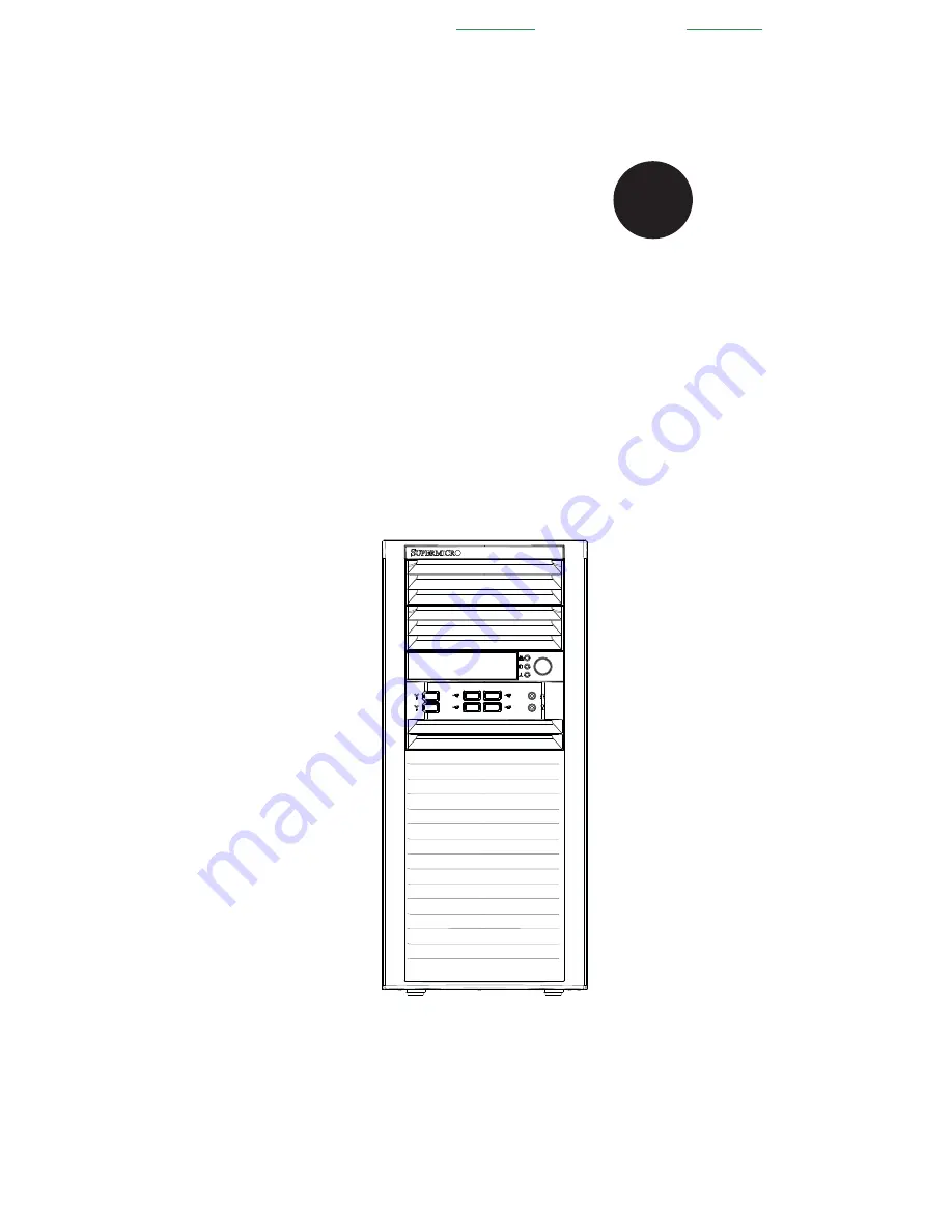
background image

®

S

uper

W

orkstation

5038A-IL


S

UPER

USER’S MANUAL

1.0

Проконсультироваться


и


купить


данное


оборудование


вы


можете


в


компании

 «

АНД

-

Системс

»  

адрес

: 125480, 

г

.

Москва

ул

.

Туристская

д

.33/1; site: https://andpro.ru 

тел

: +7 (495) 545-4870 email: [email protected] 

При


обращении


используйте


промокод

 AND-PDF 

и


получите


скидку

Summary of Contents for SuperWorkstation 5038A-IL

Page 1: ... 0 Проконсультироваться и купить данное оборудование вы можете в компании АНД Системс адрес 125480 г Москва ул Туристская д 33 1 site https andpro ru тел 7 495 545 4870 email info andpro ru При обращении используйте промокод AND PDF и получите скидку ...

Page 2: ...f any such disputes Super Micro s total liability for all claims will not exceed the price paid for the hardware product FCC Statement This equipment has been tested and found to comply with the limits for a Class A digital device pursuant to Part 15 of the FCC Rules These limits are designed to provide reasonable protection against harmful interference when the equipment is operated in a commerci...

Page 3: ...500B chassis Chapter 2 Installation This chapter describes the steps necessary to setup the SuperWorkstation 5038A IL into a rack and check out the server configuration prior to powering up the system If your system was ordered without processor and memory components this chapter will refer you to the appropriate sections of the manual for their installation Chapter 3 System Interface Refer here f...

Page 4: ...ng the serverboard Chapter 6 Advanced Chassis Setup Refer to Chapter 6 for detailed information on the SC732D4F 500B chassis You should follow the procedures given in this chapter when installing removing or reconfiguring SAS SATA or peripheral drives and when replacing system power supply units and cooling fans Chapter 7 BIOS The BIOS chapter includes an introduction to BIOS and provides detailed...

Page 5: ...v Preface Notes ...

Page 6: ...ting Supermicro 1 5 Chapter 2 Installation 2 1 Overview 2 1 2 2 Unpacking the System 2 1 2 3 Warnings and Precautions 2 1 2 3 Accessing the Inside of the System 2 2 Chapter 3 System Interface 3 1 Overview 3 1 3 2 Control Panel Button 3 1 Power 3 1 3 3 Communications Panel Components 3 1 3 4 Control Panel LEDs 3 2 NIC 3 2 HDD 3 2 Overheat Fan Fail 3 3 3 4 Drive Carrier LEDs 3 3 Chapter 4 Standardiz...

Page 7: ...Unpacking 5 1 5 2 Connecting Cables 5 2 Connecting Data Cables 5 2 Connecting Power Cables 5 2 Connecting the Control Panel 5 2 5 3 I O Ports 5 3 5 4 Processor and Heatsink Installation 5 4 Installing an LGA 1150 Processor 5 4 Installing the Heatsink 5 6 Removing the Heatsink 5 7 5 5 Installing Memory Modules 5 8 Installing Removing DIMMs 5 8 5 6 Adding PCI Add On Cards 5 11 5 7 Serverboard Detail...

Page 8: ... 2 5 Hard Drives 6 7 6 6 Installing a 3 5 Device 6 9 6 7 Installing System Fans 6 10 6 8 Installing the Front Bezel 6 12 6 9 Power Supply 6 13 Chapter 7 BIOS 7 1 Introduction 7 1 Starting BIOS Setup Utility 7 1 How To Change the Configuration Data 7 1 How to Start the Setup Utility 7 2 7 2 Main Setup 7 2 7 3 Advanced Setup Configurations 7 4 7 4 Event Logs 7 27 7 5 Boot Settings 7 29 7 6 Security ...

Page 9: ...fer to our web site for information on operating systems that have been certified for use with the SuperWorkstation 5038A IL www supermicro com In addition to the serverboard and chassis various hardware components have been included with the SuperWorkstation 5038A IL as listed below Two 12 cm PWM SuperQuiet chassis fans FAN 0124L4 Optional One active CPU heatsink SNK P0046A4 Chapter 1 Introductio...

Page 10: ...ory The X10SAE has four DIMM slots that can support up to 32 GB of Unbuffered ECC non ECC DDR3 1600 1333 1066 DIMMs See Chapter 5 for details SATA A SATA controller is integrated into the chipset to provide a SATA subsystem that supports RAID 0 1 5 and 10 The X10SAE supports six SATA 3 0 RAID 0 1 5 10 supported by PCH and two additional SATA 3 0 ports RAID 0 1 supported by ASM1061 R RAID 5 is not ...

Page 11: ...gned to support eight SATA hard drives Front Control Panel The control panel on the SuperWorkstation 5038A IL includes system monitoring LEDs and a main power button In addition two IEEE 1394a ports two USB 2 0 ports two USB 3 0 ports one audio port and one microphone port are included on the control panel See Chapter 3 for details Cooling System The SC732D4F 500B chassis has an innovative Super Q...

Page 12: ... 5GT s SATA III 10 USB 2 0 PORTS 600MB s 480Mbps USB2 0 6 SATA III PORTS RJ45 2 5GT s PCIe2 0_x1 GLAN1 i217V PCH Intel Socket H3 2 7 Gb s x2 FDI Analog port A AZALIA RealTEK ALC1150 VGA RJ45 2 5GT s PCIe2 0_x1 GLAN2 i210IT FLASH SPI 128Mb SPI Display Port HDMI DVI D TPM1 2 Header uPD720202 USB3 0 X2 HEALTH INFO COM1 2 NCT6776D LPC I O ASMedia Switch PCIe3 0_x8 8 0GT s ASM1480 PCIe3 0_x8 8 0GT s PC...

Page 13: ...ess Super Micro Computer B V Het Sterrenbeeld 28 5215 ML s Hertogenbosch The Netherlands Tel 31 0 73 6400390 Fax 31 0 73 6416525 Email sales supermicro nl General Information support supermicro nl Technical Support rma supermicro nl Customer Support Asia Pacific Address Super Micro Computer Inc 3F No 150 Jian 1st Rd Zhonghe Dist New Taipei City 23511 Taiwan R O C Tel 886 2 8226 3990 Fax 886 2 8226...

Page 14: ...SuperWorkstation 5038A IL User s Manual 1 6 Notes ...

Page 15: ...e you should file a damage claim with the carrier who delivered it Decide on a suitable location for the SuperWorkstation It should be situated in a clean dust free area that is well ventilated Avoid areas where heat electrical noise and electromagnetic fields are generated You will also need it placed near a grounded power outlet Be sure to read the Rack and Server Precautions in the next section...

Page 16: ...res two removable side covers allowing easy access to the chassis interior Removing the Side Covers 1 Disconnect the chassis from any power souce 2 Remove the two screws securing the left side cover to the chassis 3 Slide the left cover toward the rear of the chassis 4 Lift the left cover from the chassis 5 Remove the three screws securing the right side cover to the chassis 6 Slide the right cove...

Page 17: ...ront of the chassis Power 3 3 Communications Panel Components The SC732D4F features a front communication panel allowing easy access to the chassis communication ports The chassis models are equipped as follows Two USB 3 0 ports Two USB 2 0 ports Two IEEE 1394A ports One audio port One microphone port See diagram on the following page This is the main power button which is used to apply or turn of...

Page 18: ... flashing 3 4 Control Panel LEDs The control panel located on the front of the SC732 chassis has three LEDs These LEDs provide you with critical information related to different parts of the system This section explains what each LED indicates when illuminated and any corrective action you may need to take Power Button Audio 2x USB 2 0 2x USB 3 0 Mic NIC LED HDD LED OH LED 2x 1394a ...

Page 19: ...bstructing the airflow in the system or the ambient room temperature being too warm Check the routing of the cables and make sure all fans are present and operating normally You should also check to make sure that the chassis covers are installed Finally verify that the heatsinks are installed properly see Chapter 5 This LED will remain flashing or on as long as the indicated condition exists ...

Page 20: ...3 4 SuperWorkstation 5038A IL User s Manual Notes ...

Page 21: ... configuring components in the Supermicro chassis These warnings may also be found on our web site at http www supermicro com about policies safety_information cfm Warning This warning symbol means danger You are in a situation that could cause bodily injury Before you work on any equipment be aware of the hazards involved with electrical circuitry and be familiar with standard practices for preve...

Page 22: ... el número que le ayudará a encontrar el texto traducido en el apartado de traducciones que acompaña a este dispositivo GUARDE ESTAS INSTRUCCIONES IMPORTANTES INFORMATIONS DE SÉCURITÉ Ce symbole d avertissement indique un danger Vous vous trouvez dans une situation pouvant entraîner des blessures ou des dommages corporels Avant de travailler sur un équipement soyez conscient des dangers liés aux c...

Page 23: ... u aan enige apparatuur gaat werken dient u zich bewust te zijn van de bij een elektrische installatie betrokken risico s en dient u op de hoogte te zijn van de standaard procedures om ongelukken te voorkomen Gebruik de nummers aan het eind van elke waarschuwing om deze te herleiden naar de desbetreffende locatie BEWAAR DEZE INSTRUCTIES ﻓﻲ ﺍﻧﻚ ﺃﻥ ﻳﻤﻜﻦ ﺣﺎﻟﺔ ﻓﻲ ﺗﺘﺴﺒﺐ ﺍﺻﺎﺑﺔ ﺟﺴﺪﻳﺔ ﺍﻟﺮﻣﺰ ﻫﺬﺍ ﻳﻌﻨﻲ ﺧﻄﺮ ﺗ...

Page 24: ...de instalación antes de conectar el sistema a la red de alimentación Attention Avant de brancher le système sur la source d alimentation consulter les directives d installation 設置手順書 システムを電源に接続する前に 設置手順書をお読み下さい ﺍﻟ ﺇﺭﺷﺎﺩﺍﺕ ﺍﻗﺮ ﺘﺮﻛﻴﺐ ﺗﻮﺻﻴﻞ ﻗﺒﻞ ﺇﻟﻰ ﺍﻟﻨﻈﺎﻡ ﻟﻠﻄﺎﻗﺔ ﻣﺼﺪﺭ לקרוא יש למקור המערכת חיבור לפני התקנה הוראות את מתח 시스템을 전원에 연결하기 전에 설치 안내를 읽어주십시오 Waarschuwing Raadpleeg de installatie instructies v...

Page 25: ...liza el sistema de protección contra cortocircuitos o sobrecorrientes del edificio Asegúrese de que el dispositivo de protección no sea superior a 250 V 20 A Attention Pour ce qui est de la protection contre les courts circuits surtension ce produit dépend de l installation électrique du local Vérifiez que le courant nominal du dispositif de protection n est pas supérieur à 250 V 20 A על מסתמך זה ...

Page 26: ...wird bevor es auf den Chassisinnenraum zurückgreift um Systemsbestandteile anzubringen oder zu entfernen Warning The system must be disconnected from all sources of power and the power cord removed from the power supply module s before accessing the chassis interior to install or remove system components 경고 이 제품은 전원의 단락 과전류 방지에 대해서 전적으로 건물의 관련 설비에 의존합니다 보호장치의 정격이 반드시 250V 볼트 20A 암페어 를 초과하지 않도록 해야 ...

Page 27: ... ou enlever des composants de systéme חשמלי ניתוק מפני אזהרה אזהרה החשמל מקורות מכל המערכת את לנתק יש להסיר ויש מהספק החשמלי כבל את התקנ לצורך המארז של הפנימי לחלק גישה לפני ת הסר או ת רכיבים ﻓﺼﻞ ﻳﺠﺐ ﺍﻟﻨﻈﺎﻡ ﺟﻤﻴﻊ ﻣﻦ ﻣﺼﺎﺩﺭ ﺍﻟﻄﺎﻗﺔ ﻭﺇﺯﺍﻟﺔ ﺍﻟﻜﻬﺮﺑﺎء ﺳﻠﻚ ﻣﻦ ﻭﺣﺪﺓ ﺍﻣﺪﺍﺩ ﺍﻟﻄﺎﻗﺔ ﻗﺒﻞ ﺇﻟﻰ ﺍﻟﻮﺻﻮﻝ ﺍﻟﺪﺍﺧﻠﻴﺔ ﺍﻟﻤﻨﺎﻁﻖ ﻟ ﻠﻬﻴﻜﻞ ﺇﺯﺍﻟﺔ ﺃﻭ ﻟﺘﺜﺒﻴﺖ ﻣﻜﻮﻧﺎﺕ ﺍﻟﺠﻬﺎﺯ 경고 시스템에 부품들을 장착하거나 제거하기 위해서는 섀시 내부에 접근하기 전에 반드시 전원 공급장치로부터 연결...

Page 28: ...l gestattet werden Advertencia Solamente el personal calificado debe instalar reemplazar o utilizar este equipo Attention Il est vivement recommandé de confier l installation le remplacement et la maintenance de ces équipements à des personnels qualifiés et expérimentés אזהרה רש בלבד מוסמך צוות את להחליף להתקין אי הציוד עבור שירות לתת או הציוד ﻭﺍﻟﻤﺪﺭﺑﻴﻦ ﻭ ﻟﺘﺮﻛﻴﺐ ﺍﺳﺘﺒﺪﺍﻝ ﺃﻭ ﺧﺪﻣﺔ ﺍﻟﺠﻬﺎﺯ ﻫﺬﺍ ﻳﺴﻤﺢ ﺃﻥ ...

Page 29: ... in Bereichen mit beschränktem Zutritt vorgesehen Der Zutritt zu derartigen Bereichen ist nur mit einem Spezialwerkzeug Schloss und Schlüssel oder einer sonstigen Sicherheitsvorkehrung möglich Advertencia Esta unidad ha sido diseñada para instalación en áreas de acceso restringido Sólo puede obtenerse acceso a una de estas áreas mediante la utilización de una herramienta especial cerradura con lla...

Page 30: ...ﺤﻈﻮﺭﺓ ﺗﻢ ﺍﻟﻮﺻ ﻳﻤﻜﻦ ﺇﻟﻰ ﻮﻝ ﻣﻨﻄﻘﺔ ﻣﺤﻈﻮﺭﺓ ﻓﻘﻂ ﺍﺳﺘﺨﺪﺍﻡ ﺧﻼﻝ ﻣﻦ ﺧﺎﺻﺔ ﺃﺩﺍﺓ ﺃﻭ ﺃﻱ ﻟﻼ ﺃﺧﺮﻯ ﻭﺳﻴﻠﺔ ﻷﻣﺎﻥ ﻭﻣﻔﺘﺎﺡ ﻗﻔﻞ 경고 이 장치는 접근이 제한된 구역에 설치하도록 되어있습니다 특수도구 잠금 장치 및 키 또는 기타 보안 수단을 통해서만 접근 제한 구역에 들어갈 수 있습니다 Waarschuwing Dit apparaat is bedoeld voor installatie in gebieden met een beperkte toegang Toegang tot dergelijke gebieden kunnen alleen verkregen worden door gebruik te maken van speciaal gereedschap slot en...

Page 31: ...ipo o el equivalente recomendado por el fabricante Desechar las baterías gastadas según las instrucciones del fabricante אזהרה סכנת קיימת פיצוץ תקינה לא בדרך והוחלפה במידה הסוללה של להחליף יש בסוג הסוללה את מ התואם חברת מומל יצרן צת הסוללות סילוק המשומשות לבצע יש היצרן הוראות לפי ﺧﻄﺮ ﻫﻨﺎﻙ ﻣﻦ ﺍﺳﺘﺒﺪﺍﻝ ﺣﺎﻟﺔ ﻓﻲ ﺍﻧﻔﺠﺎﺭ ﺍﻟﺒﻄﺎﺭﻳﺔ ﺻﺤﻴﺤﺔ ﻏﻴﺮ ﺑﻄﺮﻳﻘﺔ ﻓﻌﻠﻴﻚ ﺍﻟﺒﻄﺎﺭﻳﺔ ﺍﺳﺘﺒﺪﺍﻝ ﻓﻘﻂ ﺍﻟﻨﻮﻉ ﺑﻨﻔﺲ ﻳﻌﺎﺩﻟﻬﺎ ﻣﺎ ﺃﻭ ﻛﻤﺎ ﺃﻭ...

Page 32: ... Cette unité peut avoir plus d une connexion d alimentation Pour supprimer toute tension et tout courant électrique de l unité toutes les connexions d alimentation doivent être débranchées Redundant Power Supplies Warning This unit might have more than one power supply connection All connections must be removed to de energize the unit 冗長電源装置 このユニッ トは複数の電源装置が接続されている場合があります ユニッ トの電源を切るためには すべての接続を取り...

Page 33: ...uidado cuando lo revise Attention Lorsque le système est en fonctionnement des tensions électriques circulent sur le fond de panier Prendre des précautions lors de la maintenance Warning Hazardous voltage or energy is present on the backplane when the system is operating Use caution when servicing ﻗﺪ ﻟﻬﺬﺍ ﻳﻜﻮﻥ ﺍﻟ ﺠﻬﺎﺯ ﺍﺗﺼﺎﻻﺕ ﻋﺪﺓ ﺑﻮﺣﺪﺍﺕ ﺍﻟﻄﺎﻗﺔ ﺍﻣﺪﺍﺩ ﺇﺯﺍﻟﺔ ﻳﺠﺐ ﺍﻻﺗﺼﺎﻻﺕ ﻛﺎﻓﺔ ﻟﻌﺰﻝ ﺍﻟ ﻮﺣﺪﺓ ﻋﻦ ﺍﻟﻜﻬﺮﺑﺎء 경...

Page 34: ...equipo debe cumplir con las normas de electricidad locales y nacionales ﻫﻨﺎﻙ ﺧﻄﺮ ﻣﻦ ﺍﻟﻜﻬﺮﺑﺎﺋﻲ ﺍﻟﺘﻴﺎﺭ ﻋﻠﻰ ﺍﻟﻤﻮﺟﻮﺩﺓ ﺃﻭﺍﻟﻄﺎﻗﺔ ﺍﻟﻠﻮﺣﺔ ﻳﻜﻮﻥ ﻋﻨﺪﻣﺎ ﺍﻟﻨﻈﺎﻡ ﻳﻌﻤﻞ ﻋﻨﺪ ﺣﺬﺭﺍ ﻛﻦ ﺧﺪﻣﺔ ﺍﻟﺠﻬﺎﺯ ﻫﺬﺍ 경고 시스템이 동작 중일 때 후면판 Backplane 에는 위험한 전압이나 에너지가 발생 합니다 서비스 작업 시 주의하십시오 Waarschuwing Een gevaarlijke spanning of energie is aanwezig op de backplane wanneer het systeem in gebruik is Voorzichtigheid is geboden tijdens het...

Page 35: ...ﺍﻧﻴﻦ ﻭﺍﻟﻮﻁﻨﻴﺔ ﺍﻟﻤﺤﻠﻴﺔ ﺍﻟﻤﺘﻌﻠﻘﺔ ﺑﺎﻟﻜﻬﺮﺑﺎء Attention L équipement doit être installé conformément aux normes électriques nationales et locales 경고 현 지역 및 국가의 전기 규정에 따라 장비를 설치해야 합니다 Waarschuwing Bij installatie van de apparatuur moet worden voldaan aan de lokale en nationale elektriciteitsvoorschriften 製品の廃棄 この製品を廃棄処分する場合 国の関係する全ての法律 条例に従い処理する必要が あります 警告 本产品的废弃处理应根据所有国家的法律和规章进行 警告 本產品的廢棄處理應根據所有國家的法律和規...

Page 36: ...nvironnement Renseignez vous auprès de l organisme compétent Warning The fans might still be turning when you remove the fan assembly from the chassis Keep fingers screwdrivers and other objects away from the openings in the fan assembly s housing Hot Swap Fan Warning המוצר סילוק אזהרה ו להנחיות בהתאם להיות חייב זה מוצר של סופי סילוק המדינה חוקי ﺍﻟﻨﻬﺎﺋﻲ ﺍﻟﺘﺨﻠﺺ ﻣﻦ ﺍﻟﻤﻨﺘﺞ ﻫﺬﺍ ﻣﻌﻪ ﺍﻟﺘﻌﺎﻣﻞ ﻳﻨﺒﻐﻲ ﻟ ﻭﻓﻘ...

Page 37: ...garde à ce que doigts tournevis et autres objets soient éloignés du logement du bloc ventilateur אזהרה חלקי את מסירים כאשר יש עובדים עדיין והמאווררים יתכן מהמארז המאוורר להרחיק ל המאוורר בתוך מהפתחים שונים עבודה וכלי האצבעות את בטוח מרחק ﺍﻟﻤﻤﻜﻦ ﻣﻦ ﺍﻟﻤﺮﺍﻭﺡ ﺃﻥ ﺗﺰﺍﻝ ﻻ ﺇﺯﺍﻟﺔ ﺗﺪﻭﺭﻋﻨﺪ ﻛﺘﻠﺔ ﺍﻟﻤﺮﻭﺣﺔ ﺍﻟﻬﻴﻜﻞ ﻣﻦ ﻳﺠﺐ ﺇﺑﻘﺎء ﺍﻷﺻﺎﺑﻊ ﻭ ﺍﻟﺒﺮﺍﻏﻲ ﻣﻔﻜﺎﺕ ﺍﻷﺷﻴﺎء ﻣﻦ ﻭﻏﻴﺮﻫﺎ ﺑﻌﻴﺪﺍ ﻋﻦ ﺍﻟﻔﺘﺤﺎﺕ ﻓﻲ ﻛﺘﻠﺔ ﺍﻟﻤﺮﻭﺣﺔ 경고 섀시로부터 팬 조립품...

Page 38: ...SA auf der Code für alle anderen elektrischen Geräte als Produkte von Supermicro nur bezeichnet gezeigt haben Advertencia Al instalar el producto utilice los cables de conexión previstos o designados los cables y adaptadores de CA La utilización de otros cables y adaptadores podría ocasionar un mal funcionamiento o un incendio Aparatos Eléctricos y la Ley de Seguridad del Material prohíbe el uso d...

Page 39: ...י על צוין שלא ﺗﺮﻛﻴﺐ ﻋﻨﺪ ﺍﺳﺘﺨﺪﺍﻡ ﻳﺠﺐ ﺍﻟﺠﻬﺎﺯ ﻭ ﺍﻟﺘﻮﺻﻴﻞ ﻛﺎﺑﻼﺕ ﺍﻟﻜﻬﺮﺑﺎﺋﻴﺔ ﺍﻟﻜﺎﺑﻼﺕ ﻭﻣﺤﻮﻻﺕ ﺍﻟﻤﺘﺮﺩﺩ ﺍﻟﺘﻴﺎﺭ ﺃﻥ ﺃﻱ ﺍﺳﺘﺨﺪﺍﻡ ﻛﺎﺑﻼﺕ ﻭﻣﺤﻮﻻﺕ ﺃﺧﺮﻯ ﻳﺘﺴﺒﺐ ﻓﻲ ﻋﻄﻞ ﺣﺪﻭﺙ ﺣﺮﻳﻖ ﺃﻭ ﺍﻟﺘﻲ ﻟﻚ ﺗﻮﻓﻴﺮﻫﺎ ﺗﻢ ﺍﻟﻤﻨﺘﺞ ﻣﻊ UL ﺃﻭ CSA ﺍﻟﻜﻬﺮﺑﺎﺋﻴﺔ ﺍﻷﺟﻬﺰﺓ ﻭﻣﻮﺍﺩ ﻗﺎﻧﻮﻥ ﺍﻟﺴﻼﻣﺔ ﺍﺳﺘﺨﺪﺍﻡ ﻳﺤﻈﺮ ﺍﻟﻜﺎﺑﻼﺕ ﻗﺒﻞ ﻣﻦ ﻣﻌﺘﻤﺪﺓ Supermicro ﺃﺟﻬﺰﺓ ﺃﺧﺮﻯ ﻛﻬﺮﺑﺎﺋﻴﺔ ﻏﻴﺮ ﺍﻟﻤﻨﺘﺠﺎﺕ ﺍﻟﻤﻌﻴﻨﺔ ﻗﺒﻞ ﻣﻦ ﻷﻱ UL CSA ﺗﺤﻤﻞ ﺍﻟﺘﻲ ﻋﻼﻣﺔ 경고 제품을 설치할 때에는 제공되거나 지정된 연결케이블과 전원케이블 AC어댑터를 사용...

Page 40: ...4 20 SuperWorkstation 5038A IL User s Manual Notes ...

Page 41: ... measures are generally sufficient to protect your equipment from electric static discharge Precautions Use a grounded wrist strap designed to prevent Electrostatic Discharge Touch a grounded metal object before removing any board from its antistatic bag Handle a board by its edges only do not touch its components peripheral chips memory modules or gold contacts When handling chips or modules avoi...

Page 42: ... locations SATA drive data cables A SATA0 A SATA1 I SATA0 I SATA5 Control Panel cable JF1 SGPIO cable T SGPIO1 T SGPIO2 Important Make sure the the cables do not come into contact with the fans Connecting Power Cables The X10SAE has a 24 pin primary power supply connector JPW1 for connection to the ATX power supply In addition an 8 pin secondary power connector JPWR2 must also be connected to your...

Page 43: ... Port 0 11 USB 2 0 Port 2 2 USB 2 0 Port 1 12 USB 2 0 Port 3 3 Keyboard Mouse 13 Gb LAN Port 2 4 DVI Port 14 SPDIF Out 5 VGA Port 15 Surround Out 6 HDMI Port 16 Center LFE Out 7 Display Port 17 Mic In 8 USB 3 0 Port 10 18 Line Out 9 USB 3 0 Port 11 19 Line In 10 Gb LAN Port 1 1 10 11 12 13 14 1 17 1 16 15 1 18 1 19 2 3 4 5 6 7 8 9 Power Button OH Fan Fail LED 1 NIC1 LED Reset Button 2 HDD LED Powe...

Page 44: ...stall the serverboard into the chassis before you install the CPU heatsinks When receiving a serverboard without a processor pre installed make sure that the plastic CPU socket cap is in place and none of the socket pins are bent otherwise contact your retailer immediately Refer to the Supermicro web site for updates on CPU support Installing an LGA 1150 Processor 1 Press the load lever to release...

Page 45: ...not rub the CPU against the surface of the socket or its pins 8 With the CPU inside the socket inspect the four corners of the CPU to make sure that the CPU is prop erly installed 9 Once the CPU is securely seated on the socket lower the CPU load plate to the socket 10 Use your thumb to gently push the socket clip down to the clip lock Warning Please save the plastic cap The serverboard must be sh...

Page 46: ...PU overheat may occur if the protective film is not removed from the heatsink 5 Apply the proper amount of thermal grease on the CPU Note if your heatsink came with a thermal pad please ignore this step 6 If necessary rearrange the wires to make sure that the wires are not pinched between the heatsink and the CPU Also make sure to keep clearance between the fan wires and the fins of the heatsink 7...

Page 47: ...e do not recommend removing theCPU or the heatsink However if neces sary please follow the instructions below to prevent damage done to the CPU or other components 1 Unplug the power cord from the pow er supply and disconnect the heatsink fan wires from the CPU fan header 2 Gently press on the fastener cap and turn it counterclockwise to make a 1 4 900 turn and pull the fastener upward to loosen i...

Page 48: ...he memory slots starting with DIMMA1 For best performance please use the memory modules of the same type and speed on the motherboard See the DIMM Instal lation Chart on the following page 2 Pull out the release tabs on the ends of a memory slot Insert each DIMM module vertically into its slot Pay attention to the notch along the bottom of the module to prevent inserting the DIMM module incor rect...

Page 49: ...chnology 2Gb DRAM Technology 4Gb DRAM Technology Single Rank UDIMM 4GB 4x1GB DIMMs 8GB 4x2GB DIMMs 16GB 4x4GB DIMMs Dual Rank UDIMMs 8GB 4x2GB DIMMs 16GB 4x4GB DIMMs 32GB 4x8GB DIMMs Notes Be sure to use memory modules of the same type same speed same frequency Mixing of memory modules of different types and speeds is not allowed Due to memory allocation to system devices the amount of memory that...

Page 50: ...ledge Base website http support microsoft com kb 888137 Possible System Memory Allocation Availability System Device Size Physical Memory Remaining Available w 4 GB Total System Memory Firmware Hub flash memory System BIOS 1 MB 3 99 Local APIC 4 KB 3 99 Area Reserved for the chipset 2 MB 3 99 I O APIC 4 Kbytes 4 KB 3 99 PCI Enumeration Area 1 256 MB 3 76 PCI Express 256 MB 256 MB 3 51 PCI Enumerat...

Page 51: ... removing the PCI slot shield for the slot you wish to populate 2 Fully seat the card into the card slot pushing down with your thumbs evenly on both sides of the card 3 Finish by using a screw to secure the top of the card shield to the chassis The PCI slot shields protect the serverboard and its components from EMI and aid in proper ventilation so make sure there is always a shield covering each...

Page 52: ...OT6 SLOT5 SLOT4 SLOT3 SLOT2 1394_2 1394_1 COM2 JSTBY1 JWD1 JPI1 I SATA2 I SATA3 I SATA4 I SATA5 JPME1 JPME2 A SATA1 3 0 X10SAE Quick Reference Jumper Description Default JBT1 CMOS Clear See Section 5 9 JI2 C1 JI2 C2 SMB to PCI Slots Off Disabled JHD_AC1 High Definition HD Audio Enable Disable Pins 1 2 Enabled JPAC1 Front Panel Audio Enable Disable Pins 1 2 Enabled JPI1 1394_1 1394_2 Enable Disable...

Page 53: ...ed Platform Module Port 80 Connector JVR1 JVR2 PWM SMB programming headers 1 2 for debug only JWOR1 Wake On Ring Header LAN1 LAN2 Gigabit RJ45 Ports LAN1 2 SP1 Internal Speaker Buzzer A SATA0 A SATA1 ASMedia Serial ATA SATA 3 0 Ports 0 1 6Gb sec I SATA0 I SATA5 Intel Serial ATA SATA 3 0 Ports 0 5 6Gb sec Slot 3 Slot 5 Slot 7 PCI Express 2 0 x1 Slots Slot 6 PCI Express 3 0 x16 Slot Slot 4 PCI Expre...

Page 54: ...utton Pin Definitions JF1 Pin Definition 1 Signal 2 3V Standby Main ATX Power Supply Connector A 24 pin main power supply connec tor JPW1 and an 8 pin CPU power connectors JPW2 are located on the serverboard These power connectors meet the SSI EPS 12V specification These power connectors must be con nected to your power supply See the table on the right for pin definitions Required Connection Proc...

Page 55: ...ections for LAN port 1 are on pins 11 and 12 and those of LAN port 2 are on pins 9 and 10 of JF1 Attach an LED cable to display network activity See the table on the right for pin definitions OH Fan Fail Indicator Status State Definition Off Normal On Overheat Flash ing Fan Fail Power On LED The Power On LED connector is lo cated on pins 15 and 16 of JF1 use JLED for a 3 pin connector This connect...

Page 56: ...xternal speaker close pins 1 4 with a cable Internal Buzzer The Internal Buzzer located at SP1 can be used to provide audible indica tions for various beep codes See the table on the right for pin definitions Internal Buzzer SP1 Pin Definition Pin Definitions Pin 1 Pos Beep In Pin 2 Neg Alarm Speaker Fan Header Pin Definitions Pin Definition 1 Ground Black 2 2 5A 12V Red 3 Tachometer 4 PWM_Control...

Page 57: ...er LED JLED1 An onboard Power LED header is located at JLED1 This Power LED header is connected to Front Control Panel located at JF1 to indicate the status of system power See the table on the right for pin definitions Onboard PWR LED Pin Definitions Pin Definition 1 VCC 2 No Connection 3 Connection to PWR LED in JF1 Ethernet Ports Two Gigabit Ethernet ports LAN1 LAN2 are located next to the HD A...

Page 58: ...3 USB_PN2 4 USB_PN3 5 USB_PP2 6 USB_PP3 7 Ground 8 Ground 9 Key 10 Ground Front Panel USB 3 0 10 11 12 13 14 15 Pin Definitions Pin Pin Signal Name Description 1 10 VBUS Power 2 11 D USB 2 0 Differential Pair 3 12 D 4 13 Ground Ground of PWR Return 5 14 StdA_SSRX SuperSpeed Receiver 6 15 StdA_SSRX Differential Pair 7 16 GND_DRAIN Ground for Signal Return 8 17 StdA_SSTX SuperSpeed Transmitter 9 18 ...

Page 59: ...round 2 Wake up TPM Header Port 80 Header A Trusted Platform Module Port 80 header is located at JTPM1 to provide TPM support and Port 80 connection Use this header to enhance system performance and data security See the table on the right for pin defini tions Standby Power Header The Standby Power header is located at STBY1 on the motherboard See the table on the right for pin defini tions Standb...

Page 60: ... features a 7 1 2 Channel High Definition Audio HDA codec that provides 10 DAC channels The HD Audio connections simultane ously supports multiple streaming 7 1 sound playback with 2 channels of independent stereo output through the front panel stereo out for front rear center and subwoofer speakers Use the Advanced software included in the CD ROM with your motherboard to enable this function BP H...

Page 61: ...jumper is on both pins and Open means the jumper is either on only one pin or completely removed Connector Pins Jumper Setting 3 2 1 3 2 1 CMOS Clear JBT1 is used to clear CMOS which will also clear any passwords Instead of pins this jumper consists of contact pads to prevent accidentally clearing the contents of CMOS To clear CMOS 1 First power down the system and unplug the power cord s 2 With t...

Page 62: ...able Disable Jumpers JPL1 JPL2 enable or disable LAN ports 1 2 on the motherboard See the table on the right for jumper settings The default setting is en abled Audio Enable Disable Jumper Settings Both Jumpers Definition Pins 1 2 Enabled Pins 2 3 Disabled Front Panel Audio Enable JPAC1 JPAC1 allows you to enable or disable front panel audio support The default position is on pins 1 and 2 to enabl...

Page 63: ... operation only in order to maintain normal power operation and management In the single operation mode online upgrade will be available via Recovery mode See the table on the right for jumper settings ME Recovery Jumper Settings Jumper Setting Definition 1 2 Normal Default 2 3 ME Recovery Manufacturer Mode Select Close pins 2 and 3 of jumper JPME2 to bypass SPI flash security and force the system...

Page 64: ...s located at LE1 on the serverboard When this LED is on the system is on Be sure to turn off the system and unplug the power cord before removing or install ing components See the table at right for more information 5 11 SATA Ports SATA Port Pin Definitions Pin Definition Pin Definition 1 Ground 2 TXP 3 TXN 4 Ground 5 RXN 6 RXP 7 Ground SATA Ports Eight SATA 3 0 ports I SATA0 1 are located on the ...

Page 65: ...bsite at http www supermicro com products Find the product page for your motherboard here where you may down load individual drivers and utilities After creating a CD DVD with the ISO files insert the disk into the CD DVD drive on your system and the display shown in Figure 5 5 should appear Note Click the icons showing a hand writing on paper to view the readme files for each item Click the compu...

Page 66: ... temperature system voltages and fan status See the figures below for examples of the SuperDoctor III interface Note The default User Name and Password for SuperDoctor III is ADMIN ADMIN Note When SuperDoctor III is first installed it adopts the temperature threshold settings that have been set in BIOS Any subsequent changes to these thresholds must be made within SuperDoctor III as the SuperDocto...

Page 67: ... comply with the regulations set up by your local hazardous waste management agency to dispose of your used battery properly Figure 5 8 Installing the Onboard Battery Figure 5 7 SuperDoctor III Interface Display Screen Remote Control Note The SuperDoctor III program and User s Manual can be downloaded from the Supermicro web site at http www supermicro com products accessories soft ware SuperDocto...

Page 68: ...5 28 SuperWorkstation 5038A IL User s Manual Notes ...

Page 69: ...e following measures are generally sufficient to protect your equipment from static discharge Precautions Use a grounded wrist strap designed to prevent static discharge Touch a grounded metal object before removing any board from its antistatic bag Handle a board by its edges only do not touch its components peripheral chips memory modules or gold contacts When handling chips or modules avoid tou...

Page 70: ...assis 3 Slide the left cover toward the rear of the chassis 4 Lift the left cover from the chassis 5 Remove the three screws securing the right side cover to the chassis 6 Slide the right cover toward the rear of the chassis 7 Lift the right cover from the chassis Warning Except for short periods of time do NOT operate the system without the cover in place The chassis cover must be in place to all...

Page 71: ...components in the chassis interior it is necessary to rotate the hard drive cage B This will provide sufficient room to install and configure the chassis components Rotating the Hard Drive Cage 1 Disconnect the chassis from any power source 2 Lift the release tab A 3 Rotate the hard disk drive cage B outward Release Tab A HDD Cage B 2 2 1 3 ...

Page 72: ...Disconnect the chassis from any power source 2 Rotate the hard drive cage outward 90 degrees as described in section 6 3 3 Disconnect all of the cables from the hard drive 4 Press the release tab on the side of the hard drive carrier that is to be re moved from the hard drive cage 5 Gently slide the hard drive carrier out of the hard drive cage Figure 6 3 Removing a Hard Drive Carrier from the Har...

Page 73: ...ommended for use in this chassis 8 Insert the new hard drive into the hard drive carrier 9 Insert the hard drive carrier into the hard drive cage sliding it towards the back of the the hard drive cage until it clicks into a locked position 10 If desired each hard drive carrier may be secured to the exterior of the hard drive cage using one optional screw 11 Rotate the hard drive cage 90 degrees in...

Page 74: ...6 6 SuperWorkstation 5038A IL User s Manual Figure 6 5 Installing a Hard Drive Carrier into the Hard Drive Cage 1 11 1 9 Optional Screw ...

Page 75: ...tem is optional The SC732 chassis must be powered down before hard drives can be removed from the hard drive carriers Removing and Installing 2 5 Hard Drives 1 Disconnect the chassis from any power source 2 Loosen the thumb screw securing the 2 5 hard drive cage to the chassis 3 Disconnect all cables from the hard drive 4 Slide the 2 5 hard drive cage out of the chassis ...

Page 76: ...rier 7 Insert the new hard drive into the hard drive carrier 8 Insert the hard drive carrier into the hard drive cage sliding it towards the back of the the hard drive cage until it clicks into a locked position 9 Slide the 2 5 hard drive cage back into the chassis and tighten the thumb screw to secure the cage 10 Connect the related cables to the hard drive Warning Only enterprise level HDDs are ...

Page 77: ...s from the bottom and pulling off the front of the chassis 2 Remove the cover plate from the 3 5 device slot on the front of the chassis 3 Install the bracket rail A onto one side of the 3 5 device by inserting the pins of the bracket into the mounting holes on the sides of the optical device 4 Slide the 3 5 device into the chassis 5 See Section 6 8 Installing the Front Bezel 1 4 1 3 1 2 1 1 Figur...

Page 78: ...r to the chassis 2 Insert the four rubber pins through mounting holes in the rear of the chassis and through the mounting holes in the rear fan 3 Pull the rubber pins through the mounting holes of the fan to secure the fan to the chassis 4 Connect the fan cable to the serverboard Figure 6 9 Installing the Rear Exhaust Fan 1 2 ...

Page 79: ...holes in the front fan 3 Pull the rubber pins through the mounting holes of the system fan to secure the fan to the chassis 4 Lower the fan into the chassis aligning the holes at the top of the front fan bracket with the holes in the chassis 5 Secure the fan to the chassis using the two screws provided 6 Connect the fan cable to the serverboard Figure 6 10 Installing the Front Cooling Fan Optional...

Page 80: ...Bezel Front Bezel Installation 1 Insert the tabs on the front bezel into the mounting holse on the front of the chassis 2 Ensure that the cover fits snugly This completes the installation of basic components in the SC732 chassis 1 1 Figure 6 11 Installing the Front Bezel ...

Page 81: ...connect the serverboard cables 3 Remove the screws securing the power supply to the chassis which are located on the rear of the chassis Set these screws aside for later use 4 Gently lift the power supply out of the chassis 5 Replace the failed power supply with an identical power supply model 6 Secure the new power supply using the screws previously set aside 7 Plug the AC power cord back into th...

Page 82: ...6 14 SuperWorkstation 5038A IL User s Manual Notes ...

Page 83: ...at can be configured Grayed out options cannot be configured Options in blue can be configured by the user The right frame displays the key legend Above the key legend is an area reserved for a text message When an option is selected in the left frame it is highlighted in white Often a text message will accompany it Note the AMI BIOS has default text messages built in Supermicro retains the option...

Page 84: ...rom a BIOS update If you have to update the BIOS do not shut down or reset the system while the BIOS is updating This is to avoid possible boot failure 7 2 Main Setup When you first enter the AMI BIOS Setup utility you will enter the Main setup screen You can always return to the Main setup screen by selecting the Main tab on the top of the screen The Main BIOS Setup screen is shown below Aptio Se...

Page 85: ...h the keyboard Press the Tab key or the arrow keys to move between fields The date must be entered in Day MM DD YY format The time is entered in HH MM SS format Note The time is in the 24 hour format For example 5 30 P M appears as 17 30 00 The following BIOS items will also be displayed Supermicro X10SAE Version Build Date Memory Information Total Memory This displays the total size of memory ava...

Page 86: ...he display mode for the Option ROM Select Keep Current to use the current AddOn ROM display setting Select Force BIOS to use the Option ROM display mode set by the system BIOS The options are Force BIOS and Keep Current Bootup Num Lock This feature selects the Power on state for the Numlock key The options are Off and On Aptio Setup Utility Copyright C 2012 American Megatrends Inc Boot Save Exit S...

Page 87: ...al boot failure The options are Disabled Legacy Boot and EFI Boot Power Configuration Watch Dog Function If enabled the Watch Dog Timer will allow the system to reboot when it is inactive for more than 5 minutes The options are Enabled and Disabled Power Button Function This feature controls how the system shuts down when the power button is pressed Select 4_Seconds_Override for the user to power ...

Page 88: ...U CPU Signature Microcode Patch Max Maximum CPU Speed Min Minimum CPU Speed CPU Speed Processor Cores Intel HT Hyper Threading Technology Intel VT x Virtualization Technology Intel SMX Trusted Execution Technology 64 bit EIST Technology CPU C3 State CPU C6 State CPU C7 State L1 Data Cache L1 Code Cache L2 Cache L3 Cache ...

Page 89: ...e Disable Bit which will allow the processor to designate areas in the system memory where an application code can execute and where it cannot thus preventing a worm or a virus from flooding illegal codes to overwhelm the processor or damage the system during an attack The default is Enabled Refer to Intel and Microsoft Web Sites for more information Intel Virtualization Technology Available when ...

Page 90: ...s feature to set the power limit for CPU1 Use the number keys on your keyboard to enter the value Enter 0 to use the manufacture default setting CPU Power Limit1 Time Available when Turbo Mode is set to Enabled This item allows the user to determine how long CPU1 should operate at the power limit set by the user for the item above Use the number keys on your keyboard to enter the value Enter 0 to ...

Page 91: ...value Enter 0 to use the manufacture default setting 4 Core Ratio Limit Available when Turbo Mode is set to Enabled This increases multiplies 4 clock speeds in the CPU core in relation to the bus speed when four CPU cores are active Press or on your keyboard to change the value Enter 0 to use the manufacture default setting Energy Performance Use this feature to select an appropriate fan setting t...

Page 92: ...lect Long to set a long delay time period during which the BIOS reports CPU C6 State ACPI C3 to the operating system The options are Short and Long CPU C7 Report Available when CPU C States is set to Enabled Select Enabled to allow the BIOS to report the CPU C7 State ACPI C3 to the operating system CPU C7 State is a processor specific low C State The options are Disabled CPU C7 and CPU C7s C7 Late...

Page 93: ... following System Agent SA information will be displayed System Agent Bridge Name VT d Capability VT d Select Enabled to enable Intel Virtualization Technology support for Direct I O VT d by reporting the I O device assignments to VMM through the DMAR ACPI Tables This feature offers fully protected I O resource sharing across the Intel platforms providing the user with greater reliability security...

Page 94: ...ally enabled The options are Auto Disabled and Enabled GTT Size Use this feature to set the memory size to be used by the graphics translation table GTT The options are 1MB and 2MB Aperture Size Use this feature to set the Aperture size which is the size of system memory re served by the BIOS for graphics device use The options are 128MB 256MB and 512 MB DVMT Pre Allocated Dynamic Video Memory Tec...

Page 95: ...Express slots is a power management protocol used to manage power consumption of serial link devices installed on PCI Exp slots during a prolonged off peak time If this item is set to Enabled PCI E ASMP will be programmed after OpROM If this item is set to Disabled the PCI E ASPM will be programmed before OpROM The options are Enabled and Disabled SLOT6 PCI E 3 0 x 16 ASPM SLOT4 PCI E 3 0 x8 in x1...

Page 96: ...OT1 SLOT2 2 0 x 1 PCI ASPM This feature configures the ASPM Active State Power Management settings for the graphics devices installed on PCI 2 0 x1 SLOT1 or SLOT2 The options are Disabled L0s L1 L0sL1 and Auto Memory Configuration This item displays the information on the memory modules installed on the motherboard Memory RC Version Memory Frequency Total Memory Memory Voltage DIMMA1 DIMMA2 DIMMB1...

Page 97: ...his feature enables or disables memory scrambler support for memory error correction The settings are Enabled and Disabled PCH IO Configuration This item displays the information for PCH IO Chip Intel PCH Rev ID USB Configuration USB Devices EHCI1 Select Enabled to enable EHCI Enhanced Host Controller Interface Controller 1 for USB 2 0 support One EHCI controller must always be enabled The setting...

Page 98: ...e EHCI driver The settings are Enabled and Disabled XHCI Mode This feature handles the operation mode for the XHCI Extensible Host Control ler Interface controller The settings are Smart Auto Auto Enabled Disabled and Manual Frontside Audio Mode This feature selects the type of audio output for the front_side audio header connection Select HD Audio for High Definition otherwise select AC 97 for le...

Page 99: ... set to AHCI the following items are displayed Serial ATA Port 0 Port 5 This item displays the information detected on the installed SATA drives on the particular SATA port Model number of drive and capacity Software Preserve Support Port 0 Port 5 Hot Plug This feature designates the port specified for hot plugging Set this item to En abled for hot plugging support which will allow the user to rep...

Page 100: ...m to Enabled for hot plugging support which will allow the user to replace a SATA drive without shutting down the system The options are Enabled and Disabled Port 0 Port 1 SATA Device Type This feature configures the selected SATA port to support either a solid state drive or hard disk drive Set this item to Enabled to enable hot plugging The options are Hard Disk Drive and Solid Sate Drive Port 0...

Page 101: ...er for a PCI Bus Signal Error Event The options are Enabled and Disabled Slot 1 PCI 33MHz OPROM Slot 2 PCI 33MHz OPROM Use this feature to enable or disable PCI slot Option ROMs This is to boot the computer using a device installed on the slot specified The options are Disabled Legacy and EFI Slot4 PCI E 3 0 x8 In x16 OPROM Slot5 PCI E 2 0 x1 OPROM Slot6 PCI E 3 0 x16 OPROM Slot7 PCI E 2 0 x1 OPRO...

Page 102: ...lock RTC does in synchronizing multimedia streams providing smooth playback and reducing the de pendency on other timestamp calculation devices such as an x86 RDTSC Instruc tion embedded in the CPU The High Performance Event Timer is used to replace the 8254 Programmable Interval Timer The options are Enabled and Disabled ACPI Sleep State This feature selects the ACPI Sleep State that the system w...

Page 103: ...r Note The computer will reboot to carry out a pending TPM operation and change TPM state for a TPM device Current Status Information This feature indicates the status of the following TPM items TPM Enabled Status TPM Active Status TPM Owner Status Intel TXT LT Support Intel TXT Trusted Execution Technology helps protect against software based attacks to ensure the security confidentiality and int...

Page 104: ...ws the user to set the Client Initiated Remote Access CIRA Timeout setting The default setting is 0 BIOS Hotkey Pressed Select Enabled to use the BIOS Hotkey feature The options are Enabled and Disabled Watch Dog Timer Select Enabled to allow AMT Advanced Management Technology to reset or power down the system if the operating system or BIOS hangs or crashes The options are Disabled and Enabled OS...

Page 105: ...de how the system controls the speeds of the onboard fans The CPU temperature and the fan speed are correlative When the CPU on die temperature increases the fan speed will also increase for effective system cooling Select Full Speed to allow the onboard fans to run at full speed of 100 Pulse Width Modulation Duty Cycle for maximum cooling This setting is recommended for special system configurati...

Page 106: ... Con sole Redirection Select VT100 to use the ASCII Character set Select VT100 to add color and function key support Select ANSI to use the Extended ASCII Char acter Set Select VT UTF8 to use UTF8 encoding to map Unicode characters into one or more bytes The options are ANSI VT100 VT100 and VT UTF8 Bits Per second Use this feature to set the transmission speed for a serial port used in Console Red...

Page 107: ...sole Redirection to prevent data loss caused by buffer overflow Send a Stop signal to stop send ing data when the receiving buffer is full Send a Start signal to start sending data when the receiving buffer is empty The options are None and Hardware RTS CTS VT UTF8 Combo Key Support Select Enabled to enable VT UTF8 Combination Key support for ANSI VT100 terminals The options are Enabled and Disabl...

Page 108: ... host computer will exchange data with the client computer which is the remote computer used by the user Out of Band Management Port The feature selects a serial port used by the Microsoft Windows Emergency Management Services EMS to communicate with a remote server The options are COM1 and COM2 Terminal Type This feature allows the user to select the target terminal emulation type for Con sole Re...

Page 109: ...t Select Screen Select Item Enter Select Change Opt F1 General Help F2 Previous Values F3 Optimized Defaults F4 Save Exit ESC Exit Press Enter to change the Smbios Event Log configuration Event Logs IPMI f Change SMBIOS Event Log Settings f View SMBIOS Event Log Aptio Setup Utility Copyright C 2012 American Megatrends Inc Version 2 15 1236 Copyright C 2012 American Megatrends Inc Flow Control This...

Page 110: ...gging to enabled or disabled The options are Disabled and Enabled MECI The Multiple Event Count Increment MECI counter counts the number of oc curences a duplicate event must happen before the MECI counter is incremented This is a numeric value The default value is 1 METW The Multiple Event Time Window METW defines number of minutes must pass between duplicate log events before MECI is incremented...

Page 111: ...ve BBS Priorities 1st Boot Device Main Advanced Security Boot Exit Select Screen Select Item Enter Select Change Opt F1 General Help F2 Previous Values F3 Optimized Defaults F4 Save Exit ESC Exit Sets the system boot order Event Logs IPMI Fast Boot Disabled Set Boot Priority 1st Boot Device CD DVD 2nd Boot Device Hard Disk 3rd Boot Device USB Hard Disk 4th Boot Device Removal 5th Boot Device Netwo...

Page 112: ...re defined boot device from which the system will boot during startup The settings are any pre defined boot device Delete Driver Option This feature allows the user to delete a previously defined boot device from which the systems boots during startup The settings are any pre defined boot device ...

Page 113: ... Setup In Setup the User will have Administrator rights The password length must be in the following range Minimum length 3 Maximum length 20 Administrator Password User Password Aptio Setup Utility Copyright C 2012 American Megatrends Inc Version 2 15 1236 Copyright C 2012 American Megatrends Inc If the Administrator password is defined ONLY this controls access to the BIOS setup ONLY If the User...

Page 114: ...on to save any changes made This will not reset reboot the system Discard Changes Select this option and press Enter to discard all the changes and return to the AMI BIOS Utility Program Restore Optimized Defaults To set this feature select Restore Defaults from the Exit menu and press Enter These are factory settings designed for maximum system stability but not for maximum performance Main Advan...

Page 115: ...tup for future use Restore User Defaults To set this feature select Restore User Defaults from the Exit menu and press En ter Use this feature to retrieve user defined settings that were saved previously Boot Override Listed on this section are other boot options for the system i e Built in EFI shell Select an option and press Enter Your system will boot to the selected boot option ...

Page 116: ...7 34 SuperWorkstation 5038A IL User s Manual Notes ...

Page 117: ...p If a fatal error oc curs you should consult with your system manufacturer for possible repairs These fatal errors are usually communicated through a series of audible beeps The numbers on the fatal error list correspond to the number of beeps for the corresponding error BIOS Error Beep Codes Beep Code LED Error Message Description 1 beep Refresh Circuits have been reset Ready to power up 5 short...

Page 118: ...A 2 SuperWorkstation 5038A IL User s Manual Notes ...

Page 119: ...ry Capacity Four DIMM slots that can support up to 32 GB of Unbuffered ECC non ECC DDR3 1600 1333 1066 DIMMs Note See the memory section in Chapter 5 for details SATA Controller Intel on chip controller for 8 port SATA 3 0 RAID supported Drive Bays Eight hot swap drive bays to house eight SATA drives Peripheral Drive Bays Two 5 25 drive bays Expansion Slots Supports the use of seven standard size ...

Page 120: ... 12 cm low noise cooling fan optional System Input Requirements AC Input Voltage 100 240 VAC Rated Input Current 7A 115V to 3 5A 240V Rated Input Frequency 50 60 Hz Power Supply Rated Output Power 500W Part PWS 502 PQ Rated Output Voltages 3 3V 15A 5V 20A 12V 17A 12V 0 5A 5Vsb 3A Operating Environment Operating Temperature 10º to 35º C 50º to 95º F Non operating Temperature 40º to 70º C 40º to 158...

Page 121: ...61000 4 4 EN 61000 4 5 EN 61000 4 6 EN 61000 4 8 EN 61000 4 11 Safety CSA EN IEC UL 60950 1 Compliant UL or CSA Listed USA and Canada CE Marking Europe California Best Management Practices Regulations for Perchlorate Materials This Perchlorate warning applies only to products containing CR Manganese Dioxide Lithium coin cells Perchlorate Material special handling may apply See www dtsc ca gov haza...

Page 122: ... perform be reasonably expected to result in significant injury or loss of life or catastrophic property damage Accordingly Supermicro dis claims any and all liability and should buyer use or sell such products for use in such ultra hazardous applications it does so entirely at its own risk Furthermore buyer agrees to fully indemnify defend and hold Supermicro harmless for and against any and all ...

Reviews: