background image

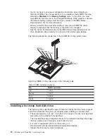
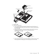
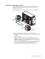
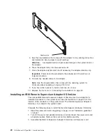
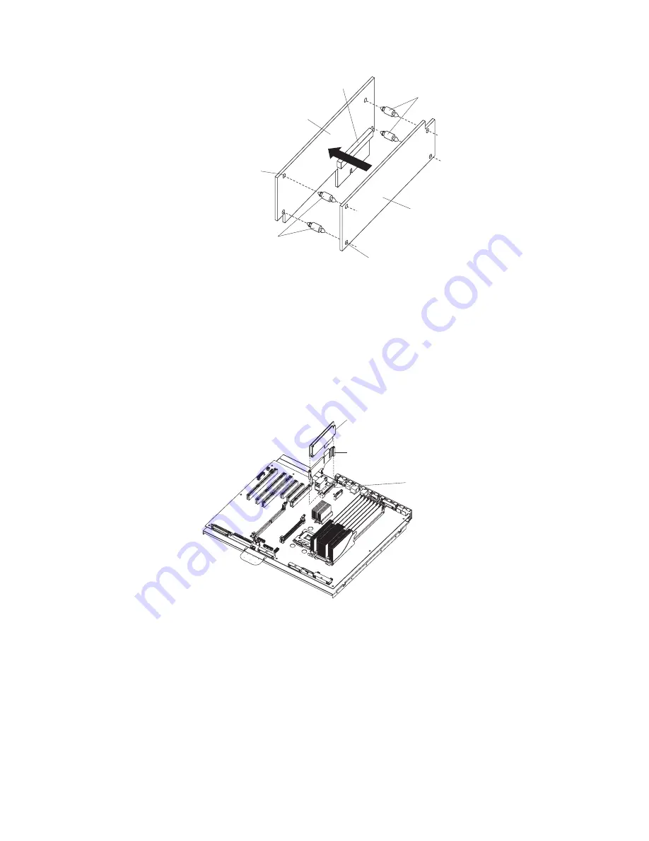
Connector

Interposer card

Mounting hole

Standoffs

Remote Supervisor
Adapter II SlimLine

Mounting hole

Standoffs

Standoffs

a.


Insert


the


standoffs


that


come


with


the


option


into


the


mounting


holes


in


the


Remote


Supervisor


Adapter


II


SlimLine.


b.


Align


the


mounting


holes


in


the


Interposer


card


with


the


standoffs;


then,


align


the


connector


on


the


card


with


the


connector


on


the


Remote


Supervisor


Adapter


II


SlimLine.


c.


Press


the


Interposer


card


and


Remote


Supervisor


Adapter


II


SlimLine


together


until


they


snap


together.

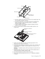
4.


Press


the


Remote


Supervisor


Adapter


II


SlimLine


guide


into


place


on


the


system


board.


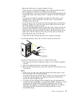
Remote Supervisor Adapter II
SlimLine guide

Remote Supervisor Adapter II
SlimLine

Remote Supervisor Adapter II
SlimLine connector


5.


Position


the


entire


adapter


assembly


so


that


the


edge


connector


on


the


Interposer


card


is


at


the


rear


of


the


server.


6.


Carefully


grasp


the


assembly


by


its


top


edge


or


upper


corners,


and


align


it


with


the


Remote


Supervisor


Adapter


II


SlimLine


guide


and


the


connector


on


the


system


board.


Attention:


Incomplete


insertion


might


cause


damage


to


the


system


board


or


the


adapter.


7.


Press


the


assembly


firmly


into


the


connector


and


under


the


retention


latch


on


the


Remote


Supervisor


Adapter


II


SlimLine


guide.


8.


If


you


have


other


options


to


install


or


remove,


do


so


now.


9.


Replace


the


air-baffle


assembly


and


cover.


Go


to


“Completing


the


installation”


on


page


22.


Chapter


2.


Installing


options


21

Summary of Contents for 8841 - eServer xSeries 236

Page 1: ...the server and install options Did the server start correctly Yes No Go to the Server Support flow chart on the reverse side of this page Start the server Did the server start correctly Yes No Cable t...

Page 2: ...fy that all optional devices you installed are on the ServerProven list at http www ibm com servers eserver serverproven compat us Is the server working correctly Is the problem solved Hardware or sof...

Page 3: ...IBM xSeries 236 Type 8841 Installation Guide...

Page 4: ...t of Limited Warranty Z125 4753 08 04 2004 on page 57 and Appendix C Notices on page 75 Third Edition September 2005 Copyright International Business Machines Corporation 2005 All rights reserved US G...

Page 5: ...n 24 Chapter 3 Server controls LEDs and power 25 Front view 25 Rear view 27 Server power features 29 Turning on the server 29 Turning off the server 30 Chapter 4 Configuring the server 31 Using the Se...

Page 6: ...ht path diagnostics LEDs 53 Appendix A Getting help and technical assistance 55 Before you call 55 Using the documentation 55 Getting help and information from the World Wide Web 56 Software service a...

Page 7: ...Japanese Voluntary Control Council for Interference VCCI statement 80 Index 81 Contents v...

Page 8: ...vi IBM xSeries 236 Type 8841 Installation Guide...

Page 9: ...lleert eerst de veiligheidsvoorschriften Ennen kuin asennat t m n tuotteen lue turvaohjeet kohdasta Safety Information Avant d installer ce produit lisez les consignes de s curit Vor der Installation...

Page 10: ...versions of the caution or danger statement in the IBM Safety Information book For example if a caution statement begins with a number 1 translations for that caution statement appear in the IBM Safe...

Page 11: ...quipment when there is evidence of fire water or structural damage v Disconnect the attached power cords telecommunications systems networks and modems before you open the device covers unless instruc...

Page 12: ...Statement 3 CAUTION When laser products such as CD ROMs DVD drives fiber optic devices or transmitters are installed note the following v Do not remove the covers Removing the covers of the laser prod...

Page 13: ...power control button on the device and the power switch on the power supply do not turn off the electrical current supplied to the device The device also might have more than one power cord To remove...

Page 14: ...el attached Hazardous voltage current and energy levels are present inside any component that has this label attached There are no serviceable parts inside these components If you suspect a problem wi...

Page 15: ...M Web site The actual procedure might vary slightly from what is described in this document 1 Go to http www ibm com support 2 Under Search technical support type xSeries 236 and click Search The serv...

Page 16: ...e keys If you plan to install the server in a rack you must purchase a Tower to Rack Kit For a list of supported options for the server see the ServerProven list at http www ibm com pc compat The IBM...

Page 17: ...f you are using a Windows operating system insert the CD into the CD ROM drive and click Start Run In the Open field type e win32 bat where e is the drive letter of the CD ROM drive and click OK If yo...

Page 18: ...lp you avoid inconvenient or problem situations v Attention These notices indicate potential damage to programs devices or data An attention notice is placed just before the instruction or situation i...

Page 19: ...45 connectors v Two serial connectors v One parallel connector v Support for one external and one optional external or internal Ultra320 SCSI connector dual channel SCSI controller with RAID capabilit...

Page 20: ...also indicate touch points on hot swap components See the instructions for removing or installing a specific hot swap component for any additional procedures that you might have to perform before you...

Page 21: ...support hot swap capability you can remove or install the component while the server is running Orange can also indicate touch points on hot swap components See the instructions for removing or insta...

Page 22: ...on Static electricity can damage the server and other electronic devices To avoid damage keep static sensitive devices in their static protective packages until you are ready to install them To reduce...

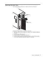
Page 23: ...URE Flange Server door Complete the following steps to remove the server door 1 Read the safety information beginning on page vii and Installation guidelines on page 7 2 Unlock and open the server doo...

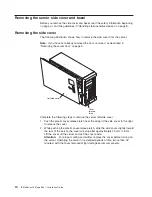
Page 24: ...omplete the following steps to remove the server left side cover 1 Push the plastic cover release latch near the edge of the side cover to the right to release the cover 2 While pushing the plastic co...

Page 25: ...rts 400 MHz 1 8 V 240 pin PC2 3200 single stacked double data rate DDR II registered synchronous dynamic random access memory SDRAM with error correcting code ECC DIMMs These DIMMs must be compatible...

Page 26: ...o install DIMMs on the system board DIMM 8 DIMM 7 DIMM 6 DIMM 5 DIMM 4 DIMM 3 DIMM 2 DIMM 1 Install the DIMMs in the order shown in the following table Table 2 DIMM installation sequence Pair DIMM con...

Page 27: ...a slim filler v The SCSI ID for each hot swap hard disk drive is printed on the bezel The following illustration shows how to install a hot swap hard disk drive Slim filler panel Hard disk drive Driv...

Page 28: ...rent level of BIOS code for the server go to http www ibm com support v Obtain an SMP capable operating system For a list of supported operating systems go to http www ibm com servers eserver serverpr...

Page 29: ...ace on the server then remove the microprocessor from the package b Rotate the locking lever on the microprocessor socket from its closed and locked position until it stops or clicks in the fully open...

Page 30: ...hen close the release lever 8 If you have other options to install or remove do so now 9 Replace the air baffle assembly and cover Go to Completing the installation on page 22 Installing an adapter Th...

Page 31: ...s The ServeRAID controller must be installed in its dedicated connector on the system board v The system scans PCI and PCI X slots 1 through 6 to assign system resources The system then starts boots t...

Page 32: ...cket Otherwise continue with the next step Adapter guide 6 Press the adapter firmly into the expansion slot lower the adapter retention latch and make sure that the latch is in the locked closed posit...

Page 33: ...t plug PCI or PCI X adapter 1 Read the safety information beginning on page vii and Installation guidelines on page 7 2 Remove the cover 3 Open the adapter retention latch and remove the expansion slo...

Page 34: ...remove do so now 10 Replace the cover Go to Completing the installation on page 22 Installing an IBM Remote Supervisor Adapter II SlimLine The optional IBM Remote Supervisor Adapter II SlimLine must b...

Page 35: ...te Supervisor Adapter II SlimLine guide Remote Supervisor Adapter II SlimLine Remote Supervisor Adapter II SlimLine connector 5 Position the entire adapter assembly so that the edge connector on the I...

Page 36: ...e static protective package containing the ServeRAID 7k adapter to any unpainted metal surface on the server Then remove the ServeRAID 7k adapter from the package 5 Turn the ServeRAID 7k adapter so th...

Page 37: ...t After you connect the cables to the selected devices route the cables for example the cables that are connected to the I O connectors through the I O cable restraint bracket The following illustrati...

Page 38: ...installed the server can operate as a symmetric multiprocessing SMP server You might have to upgrade the operating system to support SMP For more information see the section about using the ServerGui...

Page 39: ...ect button USB 3 connector Hard disk drive status LED amber Reset button Power control button Power control button shield if installed Cover release latch Model type serial number Operator information...

Page 40: ...IBM Director to light this LED remotely v Ethernet transmit receive activity LED Tx Rx 1 or Tx Rx 2 When these two green LEDs are lit they indicate that there is activity between the server and the n...

Page 41: ...nnector Connect a mouse or other PS 2 device to this connector Parallel connector Connect a parallel device to this connector Serial 1 connector Connect a 9 pin serial device to this connector USB 1 c...

Page 42: ...ates that data is being transmitted or received between the server and the network device that is connected to the connector The flashing frequency is proportional to the amount of traffic on the netw...

Page 43: ...e occurs while the server is turned on the server will restart automatically when power is restored v If the server is connected to an Advanced System Management interconnect network that contains at...

Page 44: ...em supports this feature After an orderly shutdown of the operating system the server will be turned off automatically v You can press the power control button to start an orderly shutdown of the oper...

Page 45: ...information about the supported operating system versions see the label on the CD If the ServerGuide Setup and Installation CD did not come with the server you can download the latest version from htt...

Page 46: ...rive 3 From a command line type bmc and press Enter Note The Intf ini file parameters must be set correctly for the utility program to interface with the baseboard management controller To modify the...

Page 47: ...ollow the instructions that come with the update package v If you are using a diskette complete the following steps 1 Turn on the server 2 Insert the firmware update diskette into the diskette drive 3...

Page 48: ...The SCSI RAID feature comes disabled by default You must enable it and install the device drivers before you can use it SCSI RAID configuration utilities device drivers and information are available...

Page 49: ...itial RAID level 1 configuration If you install a different type of RAID adapter in the server use the configuration method described in the instructions that come with that adapter to view or change...

Page 50: ...o select the RAID type 4 From the list of ready drives select the drives that you want to group into the array 5 Select Stripe Size 6 Type an identifier for the array 7 Select Yes if the array is boot...

Page 51: ...ServeRAID controller you must use the IBM ServeRAID Support CD that comes with the ServeRAID option Configuring the controller You can use the Configuration wizard to configure your controller The Con...

Page 52: ...m configuration To configure your controller manually select Custom configuration Using Custom configuration you can select which two physical drives you want to configure and create a hot spare drive...

Page 53: ...drives to add the drives to the array 6 Complete the following steps if you want to configure a hot spare drive a Click the Spares tab b Select the physical drive you want to designate as the hot spar...

Page 54: ...e operating system wake up support Note The server does not support changing the network boot protocol or specifying the startup order of devices through the PXE boot agent utility program Complete th...

Page 55: ...hown in the drop down list follow the instructions on the Web page to download the latest version 2 Install the IBM Director program 3 Download and install any applicable updates or interim fixes for...

Page 56: ...42 IBM xSeries 236 Type 8841 Installation Guide...

Page 57: ...mation v Troubleshooting charts These charts list problem symptoms and steps to correct the problems See Troubleshooting charts on page 46 for more information v Diagnostic programs and error messages...

Page 58: ...ing DIMM was disabled Make sure that DIMMs are supported by the server and that they are installed correctly 301 303 Keyboard and keyboard controller Make sure that the keyboard cable is connected and...

Page 59: ...cannot be installed v Make sure that there are no duplicate SCSI IDs or IRQ assignments v Make sure that the hard disk drive is connected correctly The operating system installation program continuou...

Page 60: ...or the CD ROM drive tray to work Insert the end of a straighten paper clip into the manual tray release opening If the problem remains call for service Diskette drive problems Symptom Suggested action...

Page 61: ...d attached devices v When the server is turned on air is flowing from the rear of the server at the fan grille If there is no airflow the fan is not working This can cause the server to overheat and s...

Page 62: ...IBM monitors have their own self tests If you suspect a problem with your monitor see the information that comes with the monitor for instructions for testing and adjusting the monitor If you cannot d...

Page 63: ...d update the BIOS code with the correct language If the problem remains call for service Option problems Symptom Suggested action An IBM option that was just installed does not work Make sure that v T...

Page 64: ...sure that v Each connector is assigned a unique address in the Configuration Setup Utility program and none of the serial connectors is disabled v The serial connector adapter if you installed one is...

Page 65: ...VRM S_ERR MEMORY DASD RAID NMI SERVICE PROCESSOR BUS FAN POWER SUPPLY PCI BUS 2 1 CONFIG TEMP REMIND Use the remind button on the light path diagnostic panel to acknowledge that an error has occurred...

Page 66: ...label on the left side cover Note the lit LEDs and follow the instructions on the system service label 3 LEDs on the system board To identify the component that is causing the error note the lit LED n...

Page 67: ...indicated drive v Check the LEDs on the system board and replace the indicated component v If a hard disk drive LED remains lit after being replaced call for service TEMP The system temperature has e...

Page 68: ...each adapter is removed If the problem remains call for service SERVICE PROCESSOR BUS The service processor has failed Remove ac power from the server then reconnect the server to ac power and restar...

Page 69: ...mit a request for information You can solve many problems without outside assistance by following the troubleshooting procedures that IBM provides in the online help or in the documentation that is pr...

Page 70: ...and appliances For information about which products are supported by Support Line in your country or region see http www ibm com services sl products For more information about Support Line and other...

Page 71: ...e removal of parts and their return to IBM A part that replaces a removed part will assume the warranty service status of the removed part Unless IBM specifies otherwise these warranties apply only in...

Page 72: ...an IBM Machine and other software updates from an IBM Internet Web site or from other electronic media and following the instructions that IBM provides If your problem can be resolved with a Customer...

Page 73: ...mage to your Machine only while it is 1 in IBM s possession or 2 in transit in those cases where IBM is responsible for the transportation charges Neither IBM nor your reseller are responsible for any...

Page 74: ...IGHTS WHICH VARY FROM STATE TO STATE OR JURISDICTION TO JURISDICTION Jurisdiction All of our rights duties and obligations are subject to the courts of the country in which you acquired the Machine Pa...

Page 75: ...Asuncion PERU Limitation of Liability The following is added at the end of this section In accordance with Article 1328 of the Peruvian Civil Code the limitations and exclusions specified in this sec...

Page 76: ...relates to right to sell quiet possession or clear title or the goods are of a kind ordinarily acquired for personal domestic or household use or consumption then none of the limitations in this para...

Page 77: ...the subject of the claim For purposes of this item the term Machine includes Machine Code and Licensed Internal Code LIC Arbitration The following is added under this heading Disputes arising out of o...

Page 78: ...first sentence laws of the State of New York United States of America except when local law requires otherwise PHILIPPINES Limitation of Liability Item 3 in the fifth paragraph is replaced by the fol...

Page 79: ...ntries provided the Machines have been announced and made available in such countries If you purchase a Machine in one of the Western European countries as defined above you may obtain warranty servic...

Page 80: ...atement of Limited Warranty or related to its execution including summary proceedings will be submitted to the exclusive jurisdiction of the English courts 3 in Belgium and Luxembourg all disputes ari...

Page 81: ...n the country of installation In Estonia Latvia and Lithuania all disputes arising in connection with this Statement of Limited Warranty will be finally settled in arbitration that will be held in Hel...

Page 82: ...MAGES OR 4 LOSS OF BUSINESS REVENUE GOODWILL OR ANTICIPATED SAVINGS FRANCE AND BELGIUM Limitation of Liability The following replaces the terms of this section in its entirety Except as otherwise prov...

Page 83: ...of Liability The following paragraph is added to this section The limitations and exclusions specified in the Statement of Limited Warranty will not apply to damages caused by IBM with fraud or gross...

Page 84: ...ary negligence HUNGARY Limitation of Liability The following is added at the end of this section The limitation and exclusion specified herein shall not apply to liability for a breach of contract dam...

Page 85: ...ge to data 2 special indirect or consequential loss or 3 loss of profits business revenue goodwill or anticipated savings SLOVAKIA Limitation of Liability The following is added to the end of the last...

Page 86: ...of its suppliers or resellers liable for any of the following even if IBM or they were informed of the possibility of such losses 1 loss of or damage to data 2 special indirect or consequential loss o...

Page 87: ...f your receipt of the replacement 2 On site Service IBM or your reseller will either repair or exchange the failing Machine at your location and verify its operation You must provide suitable working...

Page 88: ...e numbers below EU Country Telephone List Phone numbers are subject to change without notice For the warranty service contact telephone number in a country subsequently added to the EU and not yet ref...

Page 89: ...TY OF ANY KIND EITHER EXPRESS OR IMPLIED INCLUDING BUT NOT LIMITED TO THE IMPLIED WARRANTIES OF NON INFRINGEMENT MERCHANTABILITY OR FITNESS FOR A PARTICULAR PURPOSE Some states do not allow disclaimer...

Page 90: ...ed trademarks and logos are trademarks of Sun Microsystems Inc in the United States other countries or both Adaptec and HostRAID are trademarks of Adaptec Inc in the United States other countries or b...

Page 91: ...differ from its retail version if available and may not include user manuals or all program functionality Product recycling and disposal This unit must be recycled or discarded according to applicabl...

Page 92: ...l effects of EEE on the environment and human health due to the potential presence of hazardous substances in EEE For proper collection and treatment contact your local IBM representative Battery retu...

Page 93: ...t cause harmful interference and 2 this device must accept any interference received including interference that may cause undesired operation Industry Canada Class A emission compliance statement Thi...

Page 94: ...cation equipment Attention This is a Class A product In a domestic environment this product may cause radio interference in which case the user may be required to take adequate measures Taiwanese Clas...

Page 95: ...tivity LED 26 diskette eject button 26 documentation CD 2 door removing 9 drive hot swap installing 13 E electrical input 5 electronic emission Class A notice 79 enabling the SCSI HostRAID feature 34...

Page 96: ...power control button shield 26 power cord connector 28 Preboot Execution Environment boot agent utility program 40 problems CD ROM drive 46 diskette drive 46 expansion enclosure 46 general 47 hard dis...

Page 97: ...s USB problems 51 updating the firmware code 32 USB 1 connector 27 USB 2 connector 27 USB connector 26 using baseboard management controller utility programs 32 SCSI HostRAID to configure the controll...

Page 98: ...84 IBM xSeries 236 Type 8841 Installation Guide...

Page 99: ......

Page 100: ...Part Number 31R1188 Printed in USA 1P P N 31R1188...

Reviews: