


Chapter
3.
Server
controls,
LEDs,
and
power
This
chapter
describes
the
controls
and
light-emitting
diodes
(LEDs)
and
how
to
turn
the
server
on
and
off.
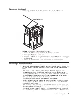
Front
view
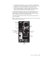
The
following
illustration
shows
the
controls,
LEDs,
and
connectors
on
the
front
of
the
server.
Note:
The
front
bezel
door
is
not
shown
so
that
the
drive
bays
are
visible.
Hard disk
drive activity
LED (green)
Diskette drive
activity LED
Diskette-
eject button
USB 3 connector
Hard disk
drive status
LED (amber)
Reset
button
Power-control
button
Power-control
button shield
(if installed)
Cover-
release
latch
Model type/serial
number
Operator
information
panel
CD-eject button
CD-ROM drive
activity LED
(green)
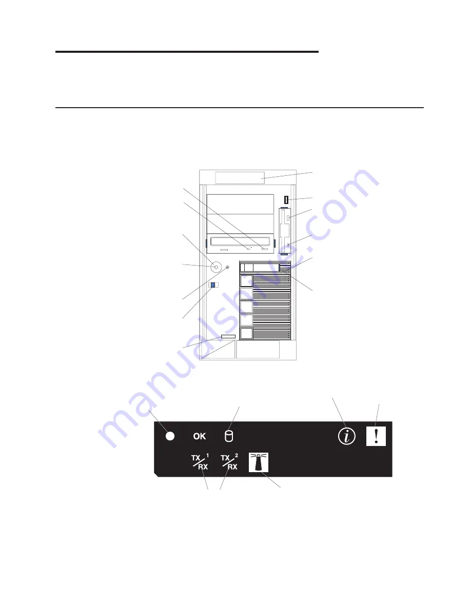
Operator
information
panel:
This
panel
contains
LEDs.
The
following
illustration
shows
the
LEDs
on
the
operator
information
panel.
System
Power-on
LED
System
Error LED
Information LED
Hard Disk Drive
Activity LED
System Locator LED
Ethernet
Transmit/Receive
LEDs
The
following
LEDs
are
on
the
operator
information
panel:
©
Copyright
IBM
Corp.
2005
25
Summary of Contents for 8841 - eServer xSeries 236
Page 3: ...IBM xSeries 236 Type 8841 Installation Guide...
Page 7: ...Japanese Voluntary Control Council for Interference VCCI statement 80 Index 81 Contents v...
Page 8: ...vi IBM xSeries 236 Type 8841 Installation Guide...
Page 56: ...42 IBM xSeries 236 Type 8841 Installation Guide...
Page 98: ...84 IBM xSeries 236 Type 8841 Installation Guide...
Page 99: ......
Page 100: ...Part Number 31R1188 Printed in USA 1P P N 31R1188...