background image

 78

Intel® Server Compute Blade SBX82: Hardware Maintenance Manual and Troubleshooting Guide 


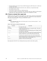
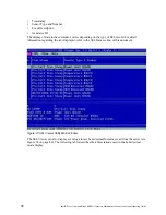
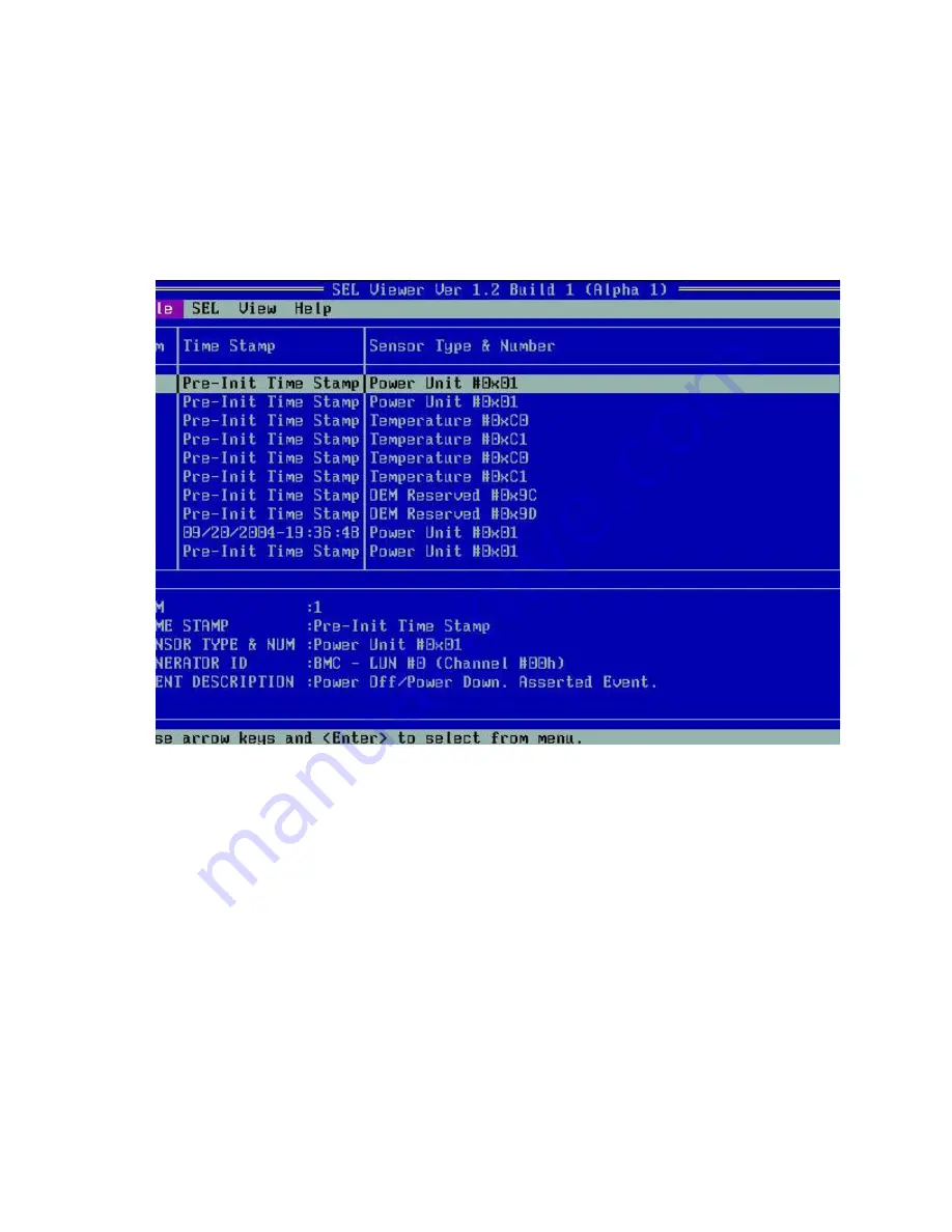
Timestamp

Sensor Type and Number

Event Description

Generator ID

The display of data in these columns varies depending on the type of SEL record. For detail 
information regarding the text displayed, refer to the SEL Data section of this document.

Figure 23 SEL Viewer Utility Main Window

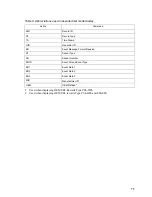
The SEL Viewer can also display event logs in raw hexadecimal format as read from the server (see 
Figure 24 on page 80). The following table describes the abbreviations used in the hexadecimal 
mode display.

Summary of Contents for 8832L1X

Page 1: ...Intel Server Compute Blade SBX82 Hardware Maintenance Manual and Troubleshooting Guide A Guide for Technically Qualified Assemblers of Intel Identified Subassemblies Products Order Number C90896 001...

Page 2: ...including liability or warranties relating to fitness for a particular purpose merchantability or infringement of any patent copyright or other intellectual property right Intel products are not desi...

Page 3: ...2 14 Using Light Path Diagnostics to troubleshoot the system board 15 3 Customer replaceable units 17 Installation guidelines 17 System reliability considerations 17 Handling static sensitive devices...

Page 4: ...ontrollers 58 Blade server Ethernet controller enumeration 59 Configuring a SCSI RAID array 59 Using the LSI Logic Configuration Utility program 60 6 Diagnostics 61 General checkout 61 Diagnostic tool...

Page 5: ...cal User Interface GUI 77 SEL Viewer Main Window 77 Pull Down Menu File 80 File Menu Item Open 80 File Menu Item Save As 81 File Menu Item Exit 81 Pull Down Menu SEL 81 SEL Menu Item Reload 81 SEL Men...

Page 6: ...I error codes 122 Temperature error messages 122 Power error messages 123 System shutdown 125 System errors 125 Temperature related system shutdown 126 DASD checkout 126 Undetermined problems 126 Prob...

Page 7: ...nt bevor Sie eine der Anweisungen ausf hren Beachten Sie hierzu auch die Sicherheitshinweise zu Intel Serverplatinen und Servergeh usen auf der Ressourcen CD oder unter http support intel com Resource...

Page 8: ...ur necktie or scarf inside clothing or fasten it with a nonconductive clip approximately 8 centimeters 3 inches from the end Do not wear jewelry chains metal frame eyeglasses or metal fasteners for yo...

Page 9: ...g testers set controls correctly and use the approved probe leads and accessories for that tester Stand on suitable rubber mats obtained locally if necessary to insulate you from grounds such as metal...

Page 10: ...h as those in the following list to provide protection that meets the specific service requirement Attach the ESD ground clip to any frame ground ground braid or green wire ground Use an ESD common gr...

Page 11: ...ed or disposed of Do not Throw or immerse into water Heat to more than 100 degrees C 212 degrees F Repair or disassemble Dispose of the battery as required by local ordinances or regulations xx CAUTIO...

Page 12: ...n the power supply do not turn off the electrical current supplied to the device The device also might have more than one power cord To remove all electrical current from the device ensure that all po...

Page 13: ...re installing the blade Safety compliance USA UL 60950 3rd Edition CSA 22 2 No 60950 Canada cUL certified 3rd Edition CSA 22 2 No 60950 for Canada product bears the single cUL mark for U S and Canada...

Page 14: ...thin the is system then the system is to be considered a Class A system In this configuration operation of this equipment in a residential area is likely to cause harmful interference NOTE This produc...

Page 15: ...hen such trouble occurs the user may be required to take corrective actions ICES 003 Canada Cet appareil num rique respecte les limites bruits radio lectriques applicables aux appareils num riques de...

Page 16: ...ercial environment so that distributors or users pay attention to this point If this product is sold or purchased improperly please exchange this product to one that can be used at home Class B device...

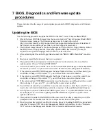
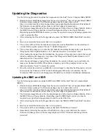
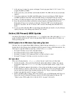
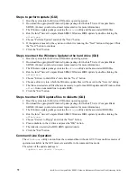
Page 17: ...ng system Performing basic troubleshooting of the blade server Record information about your Intel Server Compute Blade SBX82 in the following table NOTE The model number and serial number are on the...

Page 18: ...s A set of user labels comes with the Intel Server Compute Blade SBX82 When you install the blade server in the SBCE unit write identifying information on a label and place the label on the SBX82 unit...

Page 19: ...3 Figure 2 Label placement on the SBCE unit Important Do not place the label on the blade server itself or in any way block the ventilation holes on the blade server...

Page 20: ...ing RAS features Advanced Configuration and Power Interface ACPI Automatic error retry or recovery Automatic server restart Built in monitoring for temperature voltage hard disk drives and flash drive...

Page 21: ...on the Ethernet local area network LAN The controllers support Wake on LAN technology I O expansion The blade server comes with two connectors on the system board for an optional expansion card such a...

Page 22: ...mance impact Redundant with performance impact Non redundant You can configure and monitor the power environment using the management module For more information about configuring and using power thro...

Page 23: ...1 GB and 2 GB DIMMs four DIMM slots Service Processor Renassas 2166 supports RS 485 interface Serial over LAN SOL IPMI Drives Support for two internal small form factor SCSI drives Size Height 24 5 cm...

Page 24: ...otices indicate possible damage to programs devices or data An attention notice is placed just before the instruction or situation in which damage could occur Caution These statements indicate situati...

Page 25: ...is time the service processor in the management module is initializing therefore the power control button on the blade server does not respond NOTE While the blade server is powering up the power on L...

Page 26: ...turned off in any of the following ways You can press the power control button on the blade server behind the control panel door See Understanding the control panel and LEDs on page 11 This starts an...

Page 27: ...ttached to the SBCE unit is a PS 2 style keyboard communication with it is through the USB The operating system in the blade server must provide USB support for the blade server to recognize and use t...

Page 28: ...drive or network activity Location LED When this blue LED is lit it has been turned on remotely by the system administrator to aid in visually locating the blade server The location LED on the SBCE un...

Page 29: ...er the blade server is removed from the SBCE unit During that period of time you can relight the Light Path Diagnostics LEDs for a maximum of 25 seconds or less depending on the number of LEDs that ar...

Page 30: ...4 show the location and the settings for SW2 Figure 4 System board switch block SW2 location Table 1 Switch block 2 SW2 and settings Switch number Description SW2 Switch block Eight switches 1 BIOS ba...

Page 31: ...rror LEDs Table 2 SW4 Light Path Diagnostics LED locations LED name and location Description DIMM 1 CR6 DIMM 2 CR5 DIMM 3 CR4 DIMM 4 CR201 error There is a problem with the corresponding DIMM BMC faul...

Page 32: ...lade server If the error still exists replace the system board MIS Check the processors to make sure they are at the same speed SBRD Reboot the blade server If the error still exists replace the syste...

Page 33: ...Orange can also indicate touch points on hot swap components See the instructions for removing or installing a specific hot swap component for any additional procedures that you might have to perform...

Page 34: ...ing it down If it is necessary to set the device down place it back into its non conductive package Do not place the device on your blade server cover or on a metal surface Take additional care when h...

Page 35: ...einstall the blade server into a different bay you might need to reconfigure the blade server Complete the following steps to remove the blade server 1 If the blade server is operating shut down the o...

Page 36: ...guidelines on page 17 2 Carefully lay the blade server down on a flat non conductive surface with the cover side up 3 Press the blade cover release on each side of the blade server and lift the cover...

Page 37: ...nstalling a SCSI hard disk drive The blade server has two connectors on the system board for installing optional Ultra320 SCSI hard disk drives Each Ultra320 SCSI connector is on the same bus Dependin...

Page 38: ...uctions 5 Locate SCSI connector 0 J95 Attention Do not press on the top of the drive Pressing the top could damage the drive 6 Place the drive into the tray and push it from the rear edge of the drive...

Page 39: ...DIMMs in the following order When you install memory you must install a pair of matched DIMMs Both DIMMs in a pair must be the same size speed type and technology You can mix compatible DIMMs from var...

Page 40: ...he DIMM option to any unpainted metal surface on the SBCE unit or any unpainted metal surface on any other grounded rack component in the rack you are installing the DIMM option in for at least 2 seco...

Page 41: ...ns Always install processors that have the same cache size and type the same clock speed and identical internal and external clock frequencies including system bus speed Make sure that the processor w...

Page 42: ...el from the surface of the processor socket if one is present b Touch the non conductive package containing the new processor to any unpainted metal surface on the blade server or any unpainted metal...

Page 43: ...aligned correctly in the socket before you try to close the lever e Carefully close the lever to secure the processor in the socket 9 Install a heat sink on the processor Attention Do not set down the...

Page 44: ...card network interface type For example if you add an Ethernet expansion card to your blade server the modules in I O module bays 3 and 4 on the SBCE unit must both be compatible with the expansion ca...

Page 45: ...lade server You can install the small form factor expansion card in addition to having two SCSI hard disk drives but you cannot install a standard form factor expansion card into a blade server with t...

Page 46: ...m factor expansion card You cannot have both a drive that is connected to SCSI connector 0 and a standard form factor expansion card installed into the blade server If the drive that is connected to S...

Page 47: ...or expansion card in the blade server a Install the expansion card tray Secure the tray to the system board with the screws from the option kit as shown Figure 11 b Orient the expansion card and slide...

Page 48: ...ur blade server To avoid damage keep static sensitive devices in their non conductive packages until you are ready to install them To reduce the possibility of electrostatic discharge observe the foll...

Page 49: ...nstall the SCSI storage expansion unit on your blade server the blade server and expansion unit together occupy two blade bays in the SBCE unit For a list of SCSI hard disk drives supported by your bl...

Page 50: ...ide down onto the pins at the rear of the blade server d Pivot the expansion unit closed and press it firmly into place until the cover release latches click The connector on the expansion unit automa...

Page 51: ...format on the hard disk drives set the SCSI device scan order or set the SCSI ID for the controller The LSI Logic Configuration Utility program is part of the BIOS code on the SCSI storage expansion...

Page 52: ...e drive must have a Single Connector Attachment SCA connector Hot swap drive trays come with hot swap drives The following illustration shows how to install a SCSI hot swap hard disk drive Complete th...

Page 53: ...nit cover Complete the following steps to open the expansion unit cover 1 Read the safety information beginning on page Installation guidelines on page 17 2 Carefully lay the expansion unit down on a...

Page 54: ...card and the Gigabit Ethernet expansion card are available as small form factor and standard form factor I O expansion cards Complete the following steps to install an I O expansion card 1 Read the sa...

Page 55: ...e to be recycled or disposed of in a proper manner NOTE After you replace the battery you must reconfigure your blade server and reset the system date and time Statement 2 xx CAUTION When replacing th...

Page 56: ...the battery use your finger to press down on one side of the battery Then slide the battery from the socket The spring mechanism will push the battery out towards you as you slide it from the socket 7...

Page 57: ...ssembly if you removed it see Installing the blade server bezel assembly 2 Close the blade server cover unless you installed an expansion unit option see Closing the blade server cover on page 43 Stat...

Page 58: ...lowing steps to install the blade server bezel assembly 1 Read the safety information beginning on page vii and Installation guidelines on page 17 2 Connect the control panel cable to the control pane...

Page 59: ...g on page vii and Installation guidelines on page 17 2 If you removed the blade bezel assembly replace it now see Installing the blade server bezel assembly on page 42 for instructions 3 Lower the cov...

Page 60: ...y options that you want such as SCSI drives or memory in the blade server 3 Select the bay for the blade server Notes a If the blade server has an expansion unit installed on it the blade server and e...

Page 61: ...have to reconfigure the blade server If this is the initial installation for a blade server in the SBCE unit you must configure the blade server with the Configuration Setup Utility and install the b...

Page 62: ...46 Intel Server Compute Blade SBX82 Hardware Maintenance Manual and Troubleshooting Guide...

Page 63: ...grease applied to the underside This thermal grease is not available as a separate FRU The heat sink must be replaced when new grease is required such as when a defective microprocessor is replaced o...

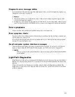
Page 64: ...sition Figure 14 until it stops or clicks in the fully open position approximately 135 angle as shown in Figure 15 Attention You must ensure that the locking lever on the microprocessor socket is in t...

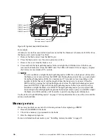
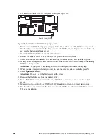
Page 65: ...ws the locations of items on the system board and describes how to replace the system board assembly System board component locations Figure 17 shows the location of the battery and of system board co...

Page 66: ...from the backup BIOS page Off boots the blade server from the primary BIOS page 2 On Wake on LAN WOL bypass On disables the bypass Off enables the bypass 3 Reserved 4 Off Power on override On forces...

Page 67: ...oes not light when the light path diagnostics button is pressed no power is available to light the blade error LEDs and they will be unable to provide any diagnostic information System board replaceme...

Page 68: ...the new system board assembly I O expansion cards reverse the steps in Installing an I O expansion card on page 28 Hard disk drives see Removing a SCSI hard disk drive on page 22 Microprocessors heat...

Page 69: ...program This section provides the instructions for starting the Configuration Setup Utility program and descriptions of the menu choices Starting the Configuration Setup Utility program Complete the f...

Page 70: ...rs Video Select this choice to view information about the integrated video controller System MAC Addresses Select this choice to set and view the MAC addresses for the Ethernet controllers on the blad...

Page 71: ...nfiguration and activates a Hot Spare Memory pair of DIMMs to replace the failed pair of DIMMs Before you can enable memory mirroring or sparing at least two pairs of DIMMs must be installed in the bl...

Page 72: ...e the changes or exit without saving them Using passwords From the System Security choice you can set change and delete a power on password If you set a power on password you must type the power on pa...

Page 73: ...ect a choice from the menu Press Esc to return to the previous menu Press the F4 key to exit 4 Follow the instructions on the screen to change the settings of the selected items then press Enter Firmw...

Page 74: ...g from Ethernet controller to I O module bay will vary based on blade server type and the operating system that is installed See Blade server Ethernet controller enumeration on page 59 for information...

Page 75: ...odule bay 1 The other Ethernet controller in the blade server is associated with the switch module in I O module bay 2 If you have installed an expansion card on a blade server communications from the...

Page 76: ...rogram 1 Turn on the blade server make sure the blade server is the owner of the keyboard video and mouse and watch the monitor screen 2 When the Press Ctrl C to start LSI Configuration Logic Utility...

Page 77: ...rror codes on page 102 3 If the blade server stops and no error is displayed go to Undetermined problems on page 126 4 For safety information see Safety and regulatory information on page vii 5 For in...

Page 78: ...ing Light path diagnostics feature Use the light path diagnostics feature to identify system errors quickly See the Light Path Diagnostics on page 108 for more information POST When you turn on the se...

Page 79: ...r codes that might be displayed are listed at Diagnostic error codes on page 99 The diagnostic text message format is as follows result test_specific_string where result is one of the following result...

Page 80: ...attached to the SBCE unit that is not controlled by the blade server you will not be able to navigate between test categories using the Next Cat and Prev Cat buttons All other functions provided by m...

Page 81: ...0 If you cannot find the problem in the error symptom charts go to Starting the diagnostic programs on page 63 to test the blade server Small computer system interface messages This information only a...

Page 82: ...25 seconds or less depending on the number of LEDs that are lit and the length of time the blade server is removed from the SBCE unit by pressing the light path diagnostics button The light path diagn...

Page 83: ...diskette drive then in unattended mode enter flash2 u r the BIOS will be updated and the system will reboot in attended mode manually reboot the system the system will boot from the floppy and follow...

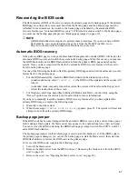
Page 84: ...enu that contains various flash update options 10 When you are prompted whether you want to move the current POST BIOS image to the backup ROM location press N Attention If you press Y the damaged BIO...

Page 85: ...M location If you select Y the current code will be flashed into the backup bank immediately 7 If the current system POST BIOS supports the Serial Number feature you will be asked if you would like to...

Page 86: ...Diagnostics Flash Update Diskette 2 of 2 diskette into drive A and select enter 8 After the second image is loaded from the diskette the system will ask you to wait while the images are flashed into...

Page 87: ...ng System The Intel Server Compute Blade SBX82 Windows Update Package includes the wflash exe file the data files for the firmware being flashed and all files needed to create a DOS flash diskette The...

Page 88: ...Intel Server Compute Blade SBX82 Windows BIOS update by double clicking the wflash exe 5 Choose Extract to Hard Drive and click the Next button 6 Choose a directory into which the Windows update files...

Page 89: ...S files 4 Open a command shell and run the Intel Server Compute Blade Windows BIOS Update with the following command line update exe x path where update exe is the downloaded update and path is the pa...

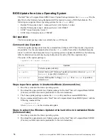
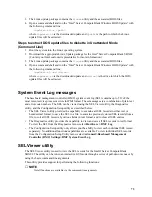
Page 90: ...tailed syntax and step by step instructions for each of the three update modes The syntax of the update package is update sh mode target Steps to perform update in Unattended Mode Command Line 1 Boot...

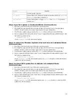
Page 91: ...s are a combination of plain text and error code numbers The SEL can be viewed using the SEL Viewer utility the Diagnostics utility and the Configuration Setup utility as described below The SEL Viewe...

Page 92: ...presented in the following table The basic command line format is selview Options NOTE The command line options listed in the following table are accessed with either the dash or the forward slash cha...

Page 93: ...nd End The display pane also supports the F5 key to move forward between columns and F6 to move backwards When the utility is first invoked the SEL records from non volatile storage on the server are...

Page 94: ...ns varies depending on the type of SEL record For detail information regarding the text displayed refer to the SEL Data section of this document Figure 23 SEL Viewer Utility Main Window The SEL Viewer...

Page 95: ...GID Generator ID ER Event Message Format Revision ST Sensor Type SN Sensor Number EDIR Event Dir and Event Type ED1 Event Data 1 ED2 Event Data 2 ED3 Event Data 3 MID Manufacturer ID1 1 Used when disp...

Page 96: ...pen This option allows you to open an existing SEL data file for viewing This option by default prompts the user to specify a file name having the sel file name extension The SEL file is displayed in...

Page 97: ...which records are currently displayed This option also provides you with the ability to select drives and directories by browsing If the SEL data cannot be saved or the file cannot be created or overw...

Page 98: ...rver as well as the entries from the SEL Viewer Main window table A dialog message prompts you for the confirmation of clearing the SEL Figure 27 Confirmation for clearing SEL SEL Menu Item Sort By Th...

Page 99: ...m in the new display mode View Menu Item Resolution Mode This option allows you to toggle between a high and low resolution mode This menu provides two sub menus Low and High to change the resolution...

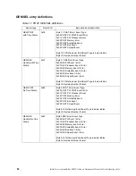
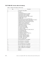
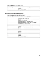
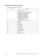
Page 100: ...also logs OEM specific messages in the BMC SEL The following tables document each OEM record ID and sensor type used by the Server Compute Blade SBX82 along with a text description of the event Using...

Page 101: ...information presented in the following tables Table 9 OEM SEL records with timestamp SEL Viewer column Text displayed Num 1 Time Stamp Time Stamp Sensor Type Number OEM data not defined Event Descript...

Page 102: ...or 0x02 SMI Memory Event Error 0x03 SMI Scalability Event Error 0x04 SMI Bus Event Error 0x05 SMI Chipset Event Error Byte 12 15 Defined per Error Event Type in below tables Byte 16 Revision Number Fo...

Page 103: ...es are defined at this time Table 12 POST PCI event error SEL format Byte Description 11 0x00 POST PCI Event Error 12 Error Type 0x00 PCI Event Error occurred Next non time stamped OEM SEL entry will...

Page 104: ...ved devices 0x0C Device title for added devices 0x0D Requested resources not available 0x0E Title for added devices 0x0F Vendor ID sub message 0x10 Device ID sub message 0x11 Previous slot sub message...

Page 105: ...format Byte Description 4 0x01 POST Processor Event Error 5 Error Type 0x00 Processor Failed BIST 0x01 Unable to Apply Microcode Patch Update 0x02 POST Does Not Support Current Stepping of Processor 6...

Page 106: ...SERR Address or Special Cycle DPE 0x02 PERR Master Read Parity Error 0x03 SERR Received Target Abort 0x04 PERR Master Write Parity Error 0x05 SERR Device Signaled SERR 0x06 PERR Slave Signaled Parity...

Page 107: ...16 Revision Number 0x00 Table 17 SMI MCA Data B1 SEL format Byte Description 4 0x01 SMI Processor Event Error 5 0x01 Data B1 6 Reserved 7 Reserved 8 11 Address high 12 15 Address low 16 Revision Numbe...

Page 108: ...Error 5 0x03 Detail C 6 Reserved 7 Reserved 8 11 MCA Status Register high 12 15 MCA Status Register low 16 Revision Number 0x00 Table 20 SMI MCA Data D SEL format Byte Description 4 0x01 SMI Processor...

Page 109: ...6 Revision Number 0x00 Table 22 SMI Sparing 2 SEL format Byte Description 4 0x02 SMI Memory Event Error 5 0x00 Sparing Event 6 0x01 Sparing Start 2 0x03 Sparing Done 2 7 Failed Row 1 8 Failed Row 2 9...

Page 110: ...EL format Byte Description 4 0x04 SMI Bus Event Error 5 Bus Type 0x00 FSB 6 0x00 FSB Fatal 0x01 FSBNonFatal 7 8 FSB FERR or NERR 9 15 Reserved 16 Revision Number 0x00 Table 25 SMI hub interface error...

Page 111: ...or FRUs to replace NOTE In tables with more than two columns multiple columns are required to describe the error symptoms Take the action or replace the FRU suggested first in the list of the right ha...

Page 112: ...board assembly 1 2 2 DMA initialization failed System board assembly 1 2 3 DMA page register write read failed System board assembly 1 2 4 RAM refresh verification failed 1 DIMM 2 System board assemb...

Page 113: ...if displayed 2 Check DIMM error LEDs 3 Check Management Module for DIMM errors 3 1 1 Timer tick interrupt failed System board assembly 3 1 2 Interval timer channel 2 failed System board assembly 3 1 3...

Page 114: ...s of the Configuration Setup Utility is set to Enabled its default setting you must restart the server three times to force the system BIOS code to reset the memory connector or bank of connectors fro...

Page 115: ...re might not have occurred For all error codes replace the FRU or take the action indicated NOTE See System on page 130 to determine which components should be replaced by a field service technician N...

Page 116: ...croprocessor 1 2 System board assembly 089 XXX 002 Failed optional microprocessor test 1 Optional microprocessor 2 2 System board assembly 165 060 000 Service Processor ASM may be busy 1 Rerun the dia...

Page 117: ...here NNN 400 to 420 excluding 406 and 407 1 Remove blade server wait 30 seconds reinsert the blade server and retry 2 Reflash or update firmware for BMC 3 System board assembly 180 XXX 000 Diagnostics...

Page 118: ...SI storage expansion unit 217 XXX 000 Failed hard disk drive test NOTE If RAID is configured the hard disk drive number refers to the RAID logical array Hard disk drive 1 217 XXX 001 Failed hard disk...

Page 119: ...lity program 2 Battery 3 System board assembly 162 Device configuration error NOTE Be sure to load the default settings and any additional desired settings then save the configuration 1 Run the Config...

Page 120: ...2 Battery 3 System board assembly 289 DIMM disabled by POST or SMI 1 Run the Configuration Setup Utility program 2 Disabled DIMM 3 System board assembly 289 Unsupported memory configuration Booting mi...

Page 121: ...rallel port configuration error 1 Run the Configuration Setup Utility program and verify that the parallel port setting is correct 2 System board assembly 11XX System board serial port 1 or 2 error 1...

Page 122: ...sk drive 4 System board assembly 1800 No more hardware interrupt available for PCI adapter 1 Run Configuration Setup to verify that the interrupt resource settings are correct 2 Failing adapter if ins...

Page 123: ...m board assembly 00019501 Microprocessor 1 is not functioning check VRM and microprocessor LEDs 1 Microprocessor 1 2 System board assembly 00019502 Microprocessor 2 is not functioning check VRM and mi...

Page 124: ...disk drive 2 SCSI backplane 3 Cable 4 System board assembly I9990305 Hard disk sector error no operating system installed Install operating system to hard disk I9990306 Timed out waiting on Boot Perm...

Page 125: ...the SBCE unit has failed If it has replace the fan 2 Make sure the room temperature is not too high See Features and specifications on page 4 for temperature information System board error The system...

Page 126: ...nts should be replaced by a field service technician CD ROM drive problems Symptom FRU action CD ROM drive is not recognized 1 Verify that All cables and jumpers are installed correctly The correct de...

Page 127: ...ick Stop 3 Select USB Mass Storage Device and click Stop 4 Click Close You can now safely switch ownership of the media tray to another blade server NOTE See System on page 130 to determine which comp...

Page 128: ...FRU action Not all drives are recognized by the hard disk drive diagnostic test Fixed Disk test 1 Remove the first drive not recognized and try the hard disk drive diagnostic test again 2 If the rema...

Page 129: ...d mouse cables are not reversed Both the computer and the monitor are turned on 2 Keyboard 3 Management module on the SBCE unit The mouse or pointing device does not work 1 Verify that The keyboard mo...

Page 130: ...memory installed 1 Verify that The memory modules are seated properly You have installed the correct type of memory If you changed the memory you updated the memory configuration with the Configuratio...

Page 131: ...rd is plugged into the SBCE power module and a working electrical outlet The monitor cables are connected properly The monitor is turned on and the Brightness and Contrast controls are adjusted correc...

Page 132: ...ic fields around other devices such as transformers appliances fluorescent lights and other monitors can cause screen jitter or wavy unreadable rolling or distorted screen images If this happens turn...

Page 133: ...SCSI storage expansion unit has been removed verify that the socket is terminated correctly The external SCSI expansion unit is turned on You must turn on the external SCSI expansion unit before turn...

Page 134: ...rver was instructed through the management module Web interface to turn on 2 If you just installed an option in the blade server remove it and restart the blade server If the blade server now turns on...

Page 135: ...the system board assembly NOTE See System on page 130 to determine which components should be replaced by a field service technician Server problems Symptom FRU action The SCSI RAID program cannot vie...

Page 136: ...mory address conflict The software is designed to operate on the computer Other software works on the computer The software that you are using works on another system If you received any error message...

Page 137: ...e switch module are blade specific If you installed an I O expansion option verify that The option is designed for the blade server You followed the installation instructions that came with the option...

Page 138: ...be causing the problem A failing SCSI device adapter drive An improper SCSI configuration Duplicate SCSI IDs in the same SCSI chain Verify that the SCSI devices are configured correctly NOTE See Syste...

Page 139: ...ge expansion option BSE 18V under recommended voltage 1 Reseat blade storage expansion option 2 Replace blade storage expansion option BSE 3 3V over recommended voltage 1 Reseat blade storage expansio...

Page 140: ...blade server 2 Replace blade server System over recommended voltage for 3 3v 1 Reseat blade server 2 Replace blade server System over recommended 5V fault 1 Reseat blade server 2 Replace blade server...

Page 141: ...which components should be replaced by a field service technician Message Action NOTE See System on page 130 to determine which components should be replaced by a field service technician Message Acti...

Page 142: ...ff due to Blade Storage Expansion option temperature 1 Ensure that the system is being properly cooled see System reliability considerations on page 17 2 Replace Blade Storage Expansion option CPU x s...

Page 143: ...rver from the SBCE web interface see the SBCE documentation for more information 3 Turn off the blade server 4 Remove the blade server and remove the cover 5 Remove or disconnect the following devices...

Page 144: ...l Operating system software Type and version level NOTE To eliminate confusion identical systems are considered identical only if they 1 Are the exact model 2 Have the same BIOS level 3 Have the same...

Page 145: ...Server Compute Blade SBX82 This parts listing supports the Intel Server Compute Blade SBX82 NOTE The illustrations in this document might differ slightly from your hardware Figure 29 Blade server expl...

Page 146: ...2 8 1 MB x 3 Microprocessor 800 3 0 1 MB x 3 Microprocessor 800 3 2 1 MB x 3 Microprocessor 800 3 4 1 MB x 3 Microprocessor 800 3 6 1 MB x 4 Front bezel with LEDs and switches x 5 Filler microprocesso...

Page 147: ...also describes the diagnostic tests that you can perform Most Intel systems and programs come with information that contains troubleshooting procedures and explanations of error messages and error cod...

Page 148: ...132 Intel Server Compute Blade SBX82 Hardware Maintenance Manual and Troubleshooting Guide...

Page 149: ...tility program 53 configuring your blade server 53 connectors battery 13 I O expansion card 13 memory 13 processor 13 SCSI 13 SCSI expansion 13 system board 13 49 controller enable or disable Ethernet...

Page 150: ...processor heat sink 17 flash memory 67 flash ROM backup page jumper 67 68 forgotten power on password bypassing 56 FRUs defined 130 G general checkout 61 Gigabit Ethernet card I O expansion card 29 G...

Page 151: ...ption 12 no beep symptoms 99 notes installing a processor 25 O opening the blade server cover 37 operating requirements minimum 127 option installing 17 option problems 117 order of installation memor...

Page 152: ...ocessor error codes 121 service processor problems 121 setting password override switch 56 small form factor expansion card installing 29 software problems 120 specifications Server Compute Blade 6 st...

Page 153: ...U undetermined problems 126 Universal Serial Bus USB problems 120 using jumpers 13 switches 13 utility Configuration Setup Utility program 53 PXE boot agent program using 57 V viewing error logs 63 W...

Page 154: ...138 Intel Server Compute Blade SBX82 Hardware Maintenance Manual and Troubleshooting Guide...

Reviews: