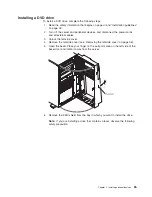
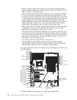

Power and signal cables for internal drives
The server uses cables to connect SATA attached, simple-swap SATA, hot-swap
SATA and hot-swap SAS devices to the power supply and to the system board.
(See “System-board internal connectors” on page 24 for the location of
system-board connectors.) Review the following information before connecting
power and signal cables to internal drives:
v
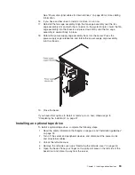
The drives that are preinstalled in the server come with power and signal cables
attached. If you replace any drives, remember which cable is attached to which
drive.
v
When you route a cable, make sure that it does not block the airflow to the rear
of the drives or over the microprocessor or DIMMs.
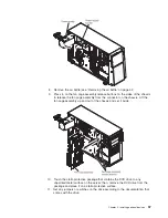
The following cables are provided:
v
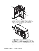
The DVD drive is attached to an ATA signal cable. The blue connector is
attached to the SATA 0 (optical drive connector) on the system board. The
connector on the other end is attached to the SATA device. The middle connector
attaches to an optional optical device or tape drive. A separate power cable
provides power to the device from the system board.
v
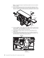
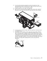
Simple-swap SATA models:
The simple-swap SATA models come with a
combination signal/power cable that connects to the connector on the system
board and the simple-swap SATA backplate to provide signal and power to the
simple-swap SATA drives. Connect the power connector on the split end of the
cable to the
Hard disk drive backplane power connector
(labeled A) on the
system board and connect the signal connector on the split end of the cable to
the
Simple-swap SATA signal cable connector
on the system board. The other
end of the combination signal/power cable has a signal cable connected to each
drive bay signal connector on the simple-swap SATA backplate and a power
cable connected to each drive bay power connector on the simple-swap SATA
backplate.
v
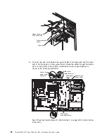
Hot-swap SAS or hot-swap SATA models:
– The 2.5-inch hot-swap SAS and hot-swap SATA models come with the
following cables to provide signal and power to the hot-swap SAS/SATA
drives:
- Four single signal cables (thick red and black) that connects to the signal
cable connectors on the hard disk drive backplanes (the backplanes are
labeled A0 and A1) and the connectors on the SAS/SATA RAID adapter
(see the ServeRAID adapters installation instructions in this document for
more cabling information).
- Two split power cables (red/yellow/black). The end of the power cable with
the single connector connects to the
Hard disk drive backplane power
connector
(the power connector labeled A) on the system board and the
end of the power cable with the two connectors, connects to the power
connectors on the hard disk drive backplanes (the backplanes are labeled
A0 and A1).
- Two split configuration signal cables (black). The end of the configuration
signal cable with the single connector connects to the
Hard disk drive
backplane configuration signal connector
(the configuration connector
labeled A) on the system board and the end of the configuration signal
cable with the two connectors, connects to the configuration signal
connectors on the hard disk drive backplanes (the backplanes are labeled
A0 and A1).
Chapter 2. Installing optional devices
69
Summary of Contents for 783722U
Page 1: ...System x3400 M2 Types 7836 and 7837 Installation and User s Guide...
Page 2: ......
Page 3: ...System x3400 M2 Types 7836 and 7837 Installation and User s Guide...
Page 8: ...vi System x3400 M2 Types 7836 and 7837 Installation and User s Guide...
Page 18: ...xvi System x3400 M2 Types 7836 and 7837 Installation and User s Guide...
Page 57: ...Chapter 2 Installing optional devices 39...
Page 122: ...104 System x3400 M2 Types 7836 and 7837 Installation and User s Guide...
Page 153: ......
Page 154: ...Part Number 69Y4170 Printed in USA 1P P N 69Y4170...


