background image

Installing


a


Single


SCSI


Bus


Cable


Use


the


following


procedure


to


install


a


single


SCSI


bus


cable


configuration


in


the


7212


Storage


Device


Enclosure:


1.


Attach


one


external


connector


to


the


bottom


SCSI


slot


on


the


rear


of


the


enclosure


chassis.


Use


the


hex


screws


provided


to


attach


the


connector.


2.


Guide


the


cable


to


the


rear


of


the


device


installed


in


Bay


B


(See


2


in


Figure


22


on


page


42)


and


connect


the


cable


to


the


device.


Note:


The


internal


SCSI


cable


routing


will


look


similar


to


the


examples


illustrated


in


Figure


22


on


page


42


and


Figure


23


on


page


42.


The


single


device


is


shown


as


an


example


installed


in


Bay


B


in


Figure


23


on


page


42.


The


single


device


can


also


be


installed


in


Bay


A.

3.


Attach


the


second


SCSI


cable


external


connector


to


the


top


SCSI


slot


on


the


rear


of


the


enclosure


chassis.


Use


the


connector


screws


provided


to


attach


the


connector.


4.


Guide


the


cable


to


the


rear


of


the


device


installed


in


Bay


A


(See


1


in


Figure


22


on


page


42)


and


connect


the


cable


to


the


device.


5.


Ensure


the


short


SCSI


bridge


cable


connectors


are


seated


securely


in


the


SCSI


cables


and


route


the


cable


around


the


vertical


support


structure


separating


the


installed


devices.


6.


Secure


the


SCSI


cables


and


cable


bridge


connectors


to


the


enclosure


chassis


using


the


cable


clamps


provided.


Refer


to


“Securing


the


Internal


SCSI


Cables”


on


page


42


for


the


placement


of


the


cable


clamps.


7.


Attach


a


terminator


to


the


end


of


the


SCSI


bus


4

.


8.


Reassemble


the


enclosure


and


return


it


to


the


rack


or


place


of


operation.

Notes:


1.


Make


sure


the


cables


do


not


interfere


with


other


cables,


fans,


the


installed


devices


or


the


enclosure


power


supply


3

.


2.


The


SCSI


cable


connections


should


be


secured


to


the


enclosure


support


structure


5


using


the


rectangular,


two-part


clamps


provided.


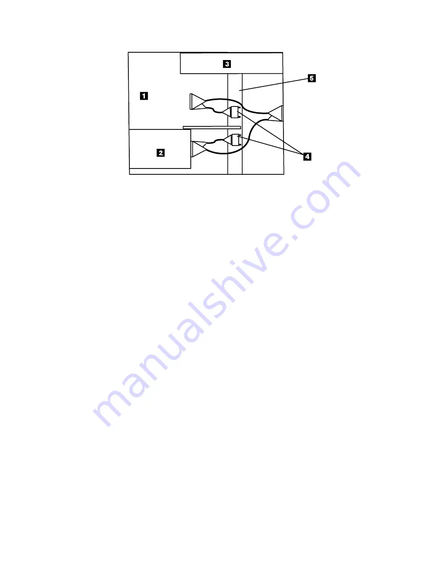
RBBTV555-0


Figure


21.


Example


of


a


Split


SCSI


bus


Cable


connection


with


One


Installed


Device


Chapter


3.


Removal


and


Replacement


41

Summary of Contents for 7212 102

Page 1: ...7212 Model 102 External Storage Device Enclosure 7212 Model 102 Storage Device Enclosure Service Guide SY44 0084 04 ERserver...

Page 2: ......

Page 3: ...7212 Model 102 External Storage Device Enclosure 7212 Model 102 Storage Device Enclosure Service Guide SY44 0084 04 ERserver...

Page 4: ...he 7212 External Storage Device Enclosure and to all subsequent releases and modifications until otherwise indicated in new editions This edition applies only to the specified model of the device Copy...

Page 5: ...tep 23 24 Step 24 25 Chapter 3 Removal and Replacement Procedures 27 Handling Static Sensitive Devices 27 Safety Considerations 27 Removing and Replacing the Cover 28 Removing a Storage Device from th...

Page 6: ...DVD ROM Drive 63 Handling Static Sensitive Devices 63 Manually Removing a DVD Disc from the Drive 64 Chapter 10 Parts Diagram and Parts List 65 How To Use This Parts List 65 Example of Parts Listing...

Page 7: ...ku Tokyo 106 0032 Japan The following paragraph does not apply to the United Kingdom or any other country where such provisions are inconsistent with local law INTERNATIONAL BUSINESS MACHINES CORPORAT...

Page 8: ...ous and any similarity to the names and addresses used by an actual business enterprise is entirely coincidental If you are viewing this information softcopy the photographs and color illustrations ma...

Page 9: ...ny rack mounted units when the stabilizer is not installed RSFTC222 CAUTION When the unit is extended its weight can turn over a rack that is not steady Before you pull the unit out of the rack ensure...

Page 10: ...rovide reasonable protection against harmful interference in a residential installation This equipment generates uses and can radiate radio frequency energy and if not installed and used in accordance...

Page 11: ...r typical residential environments to provide reasonable protection against interference with licensed communication devices Properly shielded and grounded cables and connectors IBM part number 75G595...

Page 12: ...ted States or other countries or both AIX Application System 400 AS 400 e Stylized eServer IBM iSeries Operating System 400 OS 400 pSeries RISC System 6000 RS 6000 400 Other company product and servic...

Page 13: ...ected with an installed 4mm tape drive feature Chapter 7 Servicing the SLR60 or SLR100 Tape Drive describes procedures to follow when a problem is detected with an installed SLR tape drive feature Cha...

Page 14: ...orm from a country other than the United States you can give the form to the local IBM branch office or IBM representative for postage paid mailing v If you prefer to send comments by FAX use either o...

Page 15: ...e 1 shows the 7212 Storage Enclosure with a DDS 4 4mm tape drive installed in Bay A and a DVD RAM drive installed in Bay B The 7212 Storage Enclosure has the following components on the front of the u...

Page 16: ...rt of the device feature kits since the various supported devices each have unique requirements for the audio jack connectors The audio jack connectors are supplied only with the DVD ROM Drive and the...

Page 17: ...fan failure the Pin 2 signal of the USB port will go from a high state to a low state Notes 1 The USB port pin 2 is an open collector and must be connected to a monitoring receiver that is active for...

Page 18: ...ors MES Feature Cable Adapter to 7212 102 7212 102 to 2nd Device 3 6203 6205 Integrated Ultra2 SCSI Adapter or Integrated Ultra3 SCSI Adapter LVD SE or 5703 5710 5711 5712 PCI X Adapter 0 5 m VHDCI HD...

Page 19: ...HDCI HD68 5601 9761 Yes Yes 2 5 m VHDCI HD68 5602 9762 Yes No 4 5 m VHDCI HD68 5604 9764 Yes No 10 0 m VHDCI HD68 5610 9760 Yes No 1 Use Table 4 on page 7 to determine the maximum SCSI cable length pe...

Page 20: ...0 5 m 10 5 m VXA 10 5 m 10 5 m 10 5 m 10 5 m 10 5 m SLR60 or SLR1000 10 5 m 10 5 m 10 5 m 10 5 m 10 5 m DVD RAM or DVD ROM 1 5 m 1 5 m 1 5 m 1 5 m 1 5 m 6203 6205 Integrated Ultra2 SCSI or Integrated...

Page 21: ...10 0 m 10 0 m 10 0 m VXA 10 0 m 10 0 m 10 0 m 10 0 m SLR60 or SLR100 10 0 m 10 0 m 10 0 m 10 0 m DVD RAM or DVD ROM 10 0 m 10 0 m 10 0 m 10 0 m 6203 6205 Integrated Ultra2 SCSI or Integrated Ultra3 S...

Page 22: ...watts 205 Btu hr 60 watts 240 V AC Power Factor 0 8 to 0 9 Altitude 2135 m 7000 ft Performance Specifications Dependant on device media type and SCSI bus configuration Recommended Environment Environm...

Page 23: ...tridge should only be opened by the drive and not an operator The media also is held under proper tension inside the cartridge If the cartridge is dropped this tension will be relaxed Inserting a drop...

Page 24: ...m com server mdownload Microcode can be installed by your IBM authorized service personnel or your system administrator For AS 400 and iSeries Host Systems AS 400 and iSeries system technical support...

Page 25: ...is extended its weight can turn over a rack that is not steady Before you pull the unit out of the rack ensure that a rack stabilizer is attached to the bottom front of the rack Do not pull out more...

Page 26: ...no no Step 9 Did drive complete POST yes no Fail Problem fixed Step 4 Any visual problem Step 6 Power Supply OK Step 5 Power Switch OK Fix problem and return to Step 1 yes yes yes no no no Replace po...

Page 27: ...h and return to Step 1 Replace power supply and return to Step 1 Replace fans and return to Step 1 Fix SCSI address and return to Step 1 Replace SCSI cable and return to Step 1 Replace SCSI cable and...

Page 28: ...ither light illuminates then go to Step 2 On Off This indicates normal operation Go to Step 9 Off On This indicates that there may be a fan failure Go to Step 8 Step 2 This step tests the voltage at t...

Page 29: ...or reseat the cable reassemble the enclosure and then return to Step 1 Step 5 This step checks the Power On Off switch to determine if this is the source of the problem 1 Unplug the 7212 Storage Encl...

Page 30: ...g the Power Supply on page 33 reassemble the enclosure and then return to Step 1 YES Reconnect the power supply to the internal power distribution cable and then go to Step 7 Step 7 This step checks t...

Page 31: ...serve the cooling fans on the rear of the enclosure Ensure the fans are blowing air out of the enclosure and that they are operating at a constant speed not making abnormal noises Does the fault light...

Page 32: ...p normally go to Step 11 If the enclosure powers on and appears to run normally reassemble the enclosure and then return to Step 1 YES Replace the damaged component or reseat the cable reassemble the...

Page 33: ...d button on the drive refer to the drive descriptive chapters in the 7212 Model 102 Storage Device Enclosure Setup and Operator Guide 2 Remove the used media If the media fails to unload refer to driv...

Page 34: ...cables are plugged into the drives correctly Are the SCSI addresses set correctly with the SCSI cables plugged securely and is the cable in good condition NO Replace the cable if necessary Set the SCS...

Page 35: ...e into both the host system and the 7212 Storage Enclosure then go to Step 18 YES Go to Step 18 Step 18 This step ensures that the external terminator connection is proper Inspect the terminator for d...

Page 36: ...ntify the 7212 Storage Enclosure drive features These are listed as v Differential SCSI 4mm Tape Drive v SCSI 4mm Tape Drive v SCSI DVD RAM Drive If the status of the 7212 Storage Enclosure drive feat...

Page 37: ...are properly seated If the drive has recently been replaced because of a similar problem contact your service personnel YES The problem is fixed This completes the MAPs for RS 6000 or pSeries host sy...

Page 38: ...d displays the message Re IPL of IOP was successful 8 After the IPL completes press F12 to return to the Logical Hardware Resources on System Bus screen 9 In the Description and Type Model fields of t...

Page 39: ...rform the following 1 Power off the tape drive and then power it back on to attempt to reset the error 2 Obtain a new test cartridge and repeat Step 24 3 If the test fails again replace the failing de...

Page 40: ...26 7212 Storage Device Enclosure Service Guide...

Page 41: ...o static electricity discharge When handling an electronic component wrap it an antistatic bag to prevent damage Take the following precautions v Do not remove the electronic component from the antist...

Page 42: ...r if you pull out more than one unit at a time RSFTC224 Removing and Replacing the Cover Use the following procedure to prepare the 7212 Storage Enclosure for removal or installation of a storage devi...

Page 43: ...moving and Replacing the Cover on page 28 2 Determine which device is to be removed from the 7212 Storage Enclosure Note the locations of any cables that are attached to the selected device Note the l...

Page 44: ...ckets and two mounting screws aside for use in securing a new device into the 7212 Storage Enclosure 6 Slide the device out of the 7212 Storage Enclosure RBBTV546 0 1 Figure 9 Removing the Mounting Cl...

Page 45: ...Removing and Replacing the Cover on page 28 2 Determine into which bay the device is to be installed If a device is already installed in the bay follow the procedure in Removing a Storage Device from...

Page 46: ...racket down into the 7212 Storage Enclosure so that mounting bracket engages one of the flat head screws 1 on the side of the device Screw the pan head screw into the bottom of the 7212 Storage Enclos...

Page 47: ...Enclosure Fasten the cylindrical EMC shield to the bottom of the 7212 Storage Enclosure using the clamp and screw provided in the kit 10 Route cables in the 7212 Storage Enclosure so that they do not...

Page 48: ...aking sure the external power connector aligns with the access hole v Arrange the cables so that they do not interfere with the cooling fan blades or the replacement of the cover Ensure that they do n...

Page 49: ...rd 3 Remove the two screws lockwashers and nuts 2 or 3 as appropriate that secure the cooling fan to the rear of the 7212 Storage Enclosure 4 Lift the cooling fan out of the 7212 Storage Enclosure To...

Page 50: ...of the 7212 Storage Enclosure chassis 4 Gently pull the switch assembly towards the rear of the enclosure and lift it free Note The status LED cables are mounted to the power switch bracket Refer to...

Page 51: ...e 36 3 The status LED cables are mounted to the power switch bracket Push the round LED lights forward and down and guide them carefully through the hole in the bottom of the switch bracket to free th...

Page 52: ...8 2 Disconnect the fan cables power supply cable and LED cable from the status interface card Remove the four screws 1 that secure the card to the bottom of the 7212 Storage Enclosure chassis 3 Lift t...

Page 53: ...e 7212 Storage Enclosure chassis 4 Open any clamps securing the cable or connectors and free the cable 5 Guide the cable out of the enclosure To replace the SCSI cable use one of the following procedu...

Page 54: ...enclosure chassis using the cable clamps provided Refer to Securing the Internal SCSI Cables on page 42 for the placement of the cable clamps 8 Reassemble the enclosure and return it to the rack or p...

Page 55: ...ach the connector 4 Guide the cable to the rear of the device installed in Bay A See 1 in Figure 22 on page 42 and connect the cable to the device 5 Ensure the short SCSI bridge cable connectors are s...

Page 56: ...24 on page 43 included with the assembly are used to secure the cable assembly to the enclosure This prevents the cables from moving or interfering with the device performance RBBTV552 0 Figure 22 Ex...

Page 57: ...e internally installed terminators or the SCSI cable bridge connectors in the rectangular clamps secured to the chassis support bar Lift the flat clamp cover see 3 in Figure 24 off the clamp assembly...

Page 58: ...nclosure chassis 4 With the side clips of the bracket pressed push the bracket and cable out through the back of the 7212 Storage Enclosure chassis 5 Guide the cable out of the enclosure Note Some of...

Page 59: ...ector from the rear of the drive in Bay B 3 Remove the screw that secures the torroid to the bottom of the enclosure chassis 4 Remove the screw 1 in Figure 27 that secures the external audio jacks to...

Page 60: ...46 7212 Storage Device Enclosure Service Guide...

Page 61: ...t remove the drive from its antistatic bag until you are ready to install it v With the drive still in its antistatic bag touch it to the metal frame of an electrically grounded surface v Hold the dri...

Page 62: ...ing rails by removing the four screws 1 in Figure 28 near the lower edge of the drive two on each side Access the screws through holes in the side of each rail 3 Remove the front bezel the bezel snaps...

Page 63: ...from rear This gives you access to the motor worm wheel as shown in Figure 29 Turn the hexagonal key or small screwdriver counter clockwise to release the cartridge Note This may take more than 1000 t...

Page 64: ...50 7212 Storage Device Enclosure Service Guide...

Page 65: ...not remove the drive from its antistatic bag until you are ready to install it v With the drive still in its antistatic bag touch it to the metal frame of an electrically grounded surface v Hold the...

Page 66: ...ing rails by removing the four screws 1 in Figure 30 near the lower edge of the drive two on each side Access the screws through holes in the side of each rail 3 Remove the front bezel the bezel snaps...

Page 67: ...from rear This gives you access to the motor worm wheel as shown in Figure 31 Turn the hexagonal key or small screwdriver counter clockwise to release the cartridge Note This may take more than 1000 t...

Page 68: ...54 7212 Storage Device Enclosure Service Guide...

Page 69: ...v Do not remove the drive from its antistatic bag until you are ready to install it v With the drive still in its antistatic bag touch it to the metal frame of an electrically grounded surface v Hold...

Page 70: ...he Enclosure on page 29 2 Remove the front bezel the bezel snaps on by doing the following a Use a small screwdriver to press the bezel tabs 1 on each side of the drive b Rotate the bottom of the beze...

Page 71: ...reel 8 Repeat steps 6 and 7 until all of the tape media is wound onto the cartridge take up wheel 9 When the tape is completely rewound into the cartridge turn the load motor clockwise until the tape...

Page 72: ...n in then the bezel is installed improperly Remove the bezel and repeat the bezel installation procedure insuring that the door is kept open while installing the bezel Attention Attempting to force th...

Page 73: ...he drive carefully to prevent permanent damage Manually Removing a Tape Cartridge If a power failure or a drive failure prevents the tape cartridge from ejecting the cartridge can be removed manually...

Page 74: ...ght The tape unit is now in Standby position 7 Locate the hook shaped metal rod A inside the tape unit in the upper left corner 8 Insert a pointed object for example a pen or screwdriver into the tape...

Page 75: ...it has been away from the environment or for 24 hours whichever is less Handling Static Sensitive Devices Attention Storage devices drives are sensitive to static electricity discharge To prevent dam...

Page 76: ...nch into the manual unload hole until resistance is met then push to unlatch the DVD disc tray Figure 35 shows the manual unload hole 1 in the DVD RAM drive The metal rod should have a diameter of 2 m...

Page 77: ...s it has been away from the environment or for 24 hours whichever is less Handling Static Sensitive Devices Attention Storage devices drives are sensitive to static electricity discharge To prevent da...

Page 78: ...nch into the manual unload hole until resistance is met then push to unlatch the DVD disc tray Figure 37 shows the manual unload hole 1 in the DVD ROM drive The metal rod should have a diameter of 2 m...

Page 79: ...the illustration R Restricted in the Units column indicates that the part has a restricted availability Indent The indenture is marked by a series of dots located before the parts description The ind...

Page 80: ...Assembly 1 Parts Diagram RBBTW526 3 1 2 3 4 5 26 6 7 8 9 10 11 12 24 25 14 15 16 17 18 19 13 20 21 22 23 66 7212 Storage Device Enclosure Service Guide...

Page 81: ...Label LED 23 19P4019 1 Label IBM logo 24 19P5078 2 Cable clamp base rectangular C clamp 25 19P5079 2 Cable clamp cover rectangular C clamp 26 59F4585 1 Toroid 00 19P4756 5 Cable clamp kwik clip 5 16 i...

Page 82: ...dge 00 59H4457 1 DDS 4 test cartridge 00 19P4879 1 VXA Test cartridge 00 19P4880 1 VXA Cleaning cartridge 00 35L0967 1 SLR Test cartridge 00 35L0844 1 SLR Cleaning cartridge 00 81F8902 1 Test CD ROM d...

Page 83: ...proved by the appropriate testing organization for the specific countries where they are used For units set at 230 V outside of U S Use a Cable Set consisting of a minimum 18 AWG cable and grounding t...

Page 84: ...k Denmark 5 14F0015 South Africa Bangladesh Burma Pakistan South Africa Sri Lanka 6 14F0033 United Kingdom Bahrain Bermuda Brunei Channel Islands Cyprus Ghana Hong Kong India Iraq Ireland Jordan Kenya...

Page 85: ...t a possible electrical shock when adding or removing any devices to or from the system ensure that the power cords for those devices are unplugged before the signal cables are connected or disconnect...

Page 86: ...when possible to connect or disconnect signal cables RSFTD004 DANGER To prevent a possible electrical shock when adding or removing any devices to or from the system ensure that the power cords for th...

Page 87: ...test see Chapter 2 Maintenance Analysis Procedures on page 11 for more information If problems persist contact your service representative Note The Safety Information Label located on top of the powe...

Page 88: ...74 7212 Storage Device Enclosure Service Guide...

Page 89: ...information in this book is Very Satisfied Satisfied Neutral Dissatisfied Very Dissatisfied Accurate h h h h h Complete h h h h h Easy to find h h h h h Easy to understand h h h h h Well organized h h...

Page 90: ...lopment Department 542 3605 Hwy 52 North Rochester Minnesota 55901 7829 _ _ _ _ _ _ _ _ _ _ _ _ _ _ _ _ _ _ _ _ _ _ _ _ _ _ _ _ _ _ _ _ _ _ _ _ _ _ _ _ _ _ _ _ _ _ _ _ _ _ _ _ _ _ _ _ _ _ _ _ _ _ _ _...

Page 91: ......

Page 92: ...Part Number 24R1295 Printed in USA SY44 0084 04 1P P N 24R1295...

Reviews: