


Step
6
This
step
checks
the
power
supply
voltage
levels
as
the
possible
source
of
the
problem.
1.
Press
the
power
switch
to
turn
off
the
power
to
the
7212
Storage
Enclosure.
2.
Unplug
the
7212
Storage
Enclosure
from
the
electrical
outlet.
3.
Disconnect
the
power
supply
connector
(J1)
from
the
internal
power
distribution
cable.
4.
Connect
the
power
cable
to
both
the
7212
Storage
Enclosure
and
to
the
electrical
outlet.
5.
Press
the
power
switch
to
turn
on
the
power.
6.
Ensure
the
fan
is
operating
on
the
power
supply.
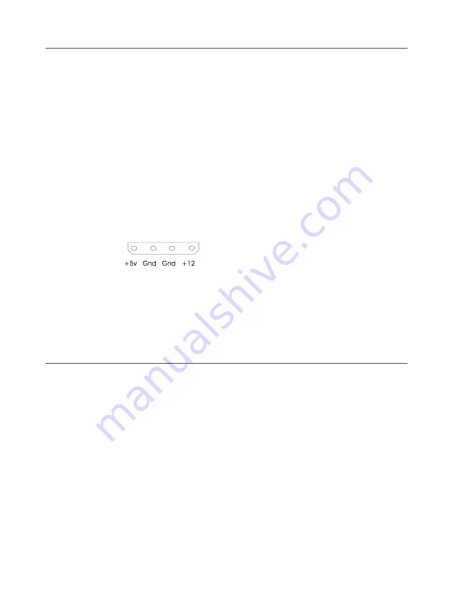
7.
On
the
power
supply
connector
J1
(see
Figure
5),
check
the
following:
v
The
+12V
signal
falls
between
a
minimum
of
+11.5
volts
and
a
maximum
of
+12.6
volts
v
The
+5V
signal
falls
between
a
minimum
of
+4.8
volts
and
a
maximum
of
+5.25
volts
Are
the
voltages
good,
and
is
the
power
supply
fan
operating?
NO
Replace
the
power
supply
(see
“Removing
and
Replacing
the
Power
Supply”
on
page
33),
reassemble
the
enclosure,
and
then
return
to
Step
1.
YES
Reconnect
the
power
supply
to
the
internal
power
distribution
cable
and
then
go
to
Step
7.
Step
7
This
step
checks
the
LED
cable
as
the
possible
source
of
the
problem.
1.
Press
the
power
switch
to
turn
off
the
power
to
the
7212
Storage
Enclosure.
2.
Unplug
the
7212
Storage
Enclosure
from
the
electrical
outlet.
3.
Disconnect
the
LED
cable
from
the
status
interface
card.
4.
Connect
the
power
cable
to
both
the
7212
Storage
Enclosure
and
to
the
electrical
outlet.
5.
Press
the
power
switch
to
turn
on
the
power
to
the
enclosure.
6.
Check
the
voltage
on
the
status
interface
card
J1
connector
pins
with
the
7212
cooling
fans
set
to
the
states
listed
in
Table
8
on
page
17.
This
table
lists
the
front
panel
status
light
states
that
would
occur
if
the
LED
cable
is
plugged
into
the
J1
connector.
Note:
The
fans
can
be
turned
to
an
OFF
state
by
disconnecting
the
fan
cable
from
the
status
interface
board.
Figure
5.
Power
Supply
Connector
J1
16
7212
Storage
Device
Enclosure
Service
Guide
Summary of Contents for 7212 102
Page 2: ......
Page 40: ...26 7212 Storage Device Enclosure Service Guide...
Page 60: ...46 7212 Storage Device Enclosure Service Guide...
Page 64: ...50 7212 Storage Device Enclosure Service Guide...
Page 68: ...54 7212 Storage Device Enclosure Service Guide...
Page 88: ...74 7212 Storage Device Enclosure Service Guide...
Page 91: ......
Page 92: ...Part Number 24R1295 Printed in USA SY44 0084 04 1P P N 24R1295...


