
hardware installation
84
Multi–Platform Interface Feature Operation Guide
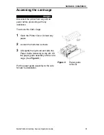
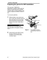
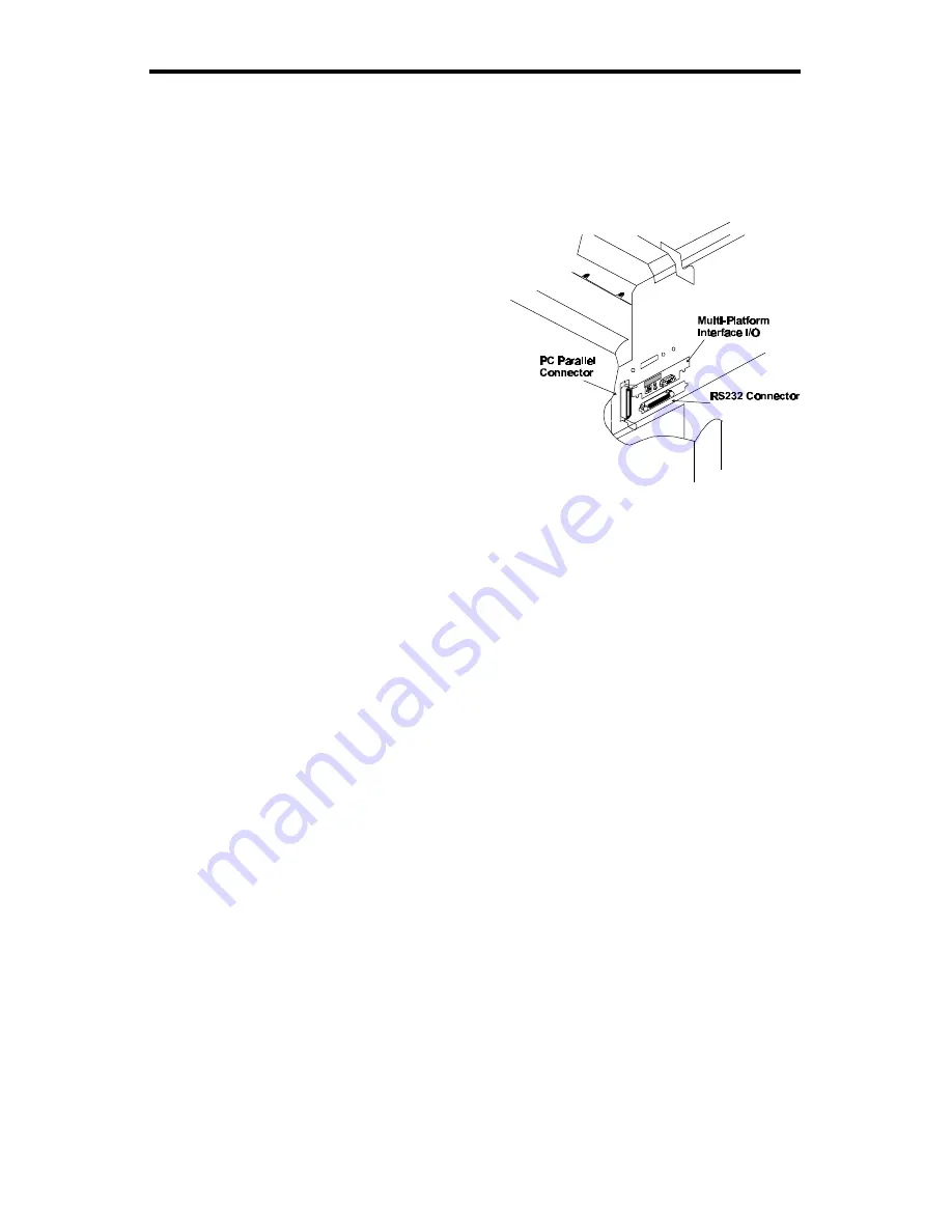
Figure 9
Printer interface area
after installing the
Multi-Platform
Interface
4
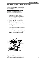
Using two of the supplied Phillips
screws, mount the controller I/O
assembly in the area formerly
occupied by the printer's interface
expansion slot cover.
Use the third Phillips screw to mount
the Multi-Platform PCBA to the
standoff, installed earlier, located on
the printer’s mother board next to
connector J111. (See
Figure 8
)
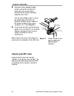
5
Connect the printer’s Centronics data
cable to the connector P3 on the Multi-
Platform Interface PCBA. This will
supply connection to the PC
environment.
Make certain that none of the cables are
pinched by the installation of the MPI card.
Attaching the MPI Label
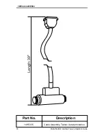
Attach the MPI Label, part number
145594, on the printer, near the MPI. This
label provides information about the MPI
connections and is needed, if service is
required.
Summary of Contents for 6400 Series
Page 12: ...x...
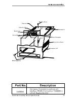
Page 89: ...hardware assemblies Multi Platform Interface Feature Operation Guide 75 Hardware Assemblies...
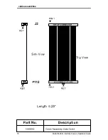
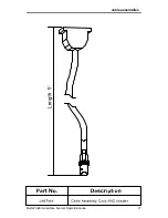
Page 90: ...cable assemblies 76 Multi Platform Interface Feature Operation Guide Cable Assemblies...
Page 91: ...cable assemblies Multi Platform Interface Feature Operation Guide 77...
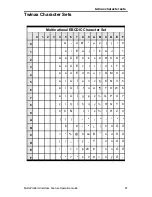
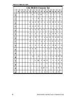
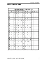
Page 109: ...coax character sets Multi Platform Interface Feature Operation Guide 95...
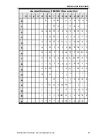
Page 110: ...coax character sets 96 Multi Platform Interface Feature Operation Guide...


