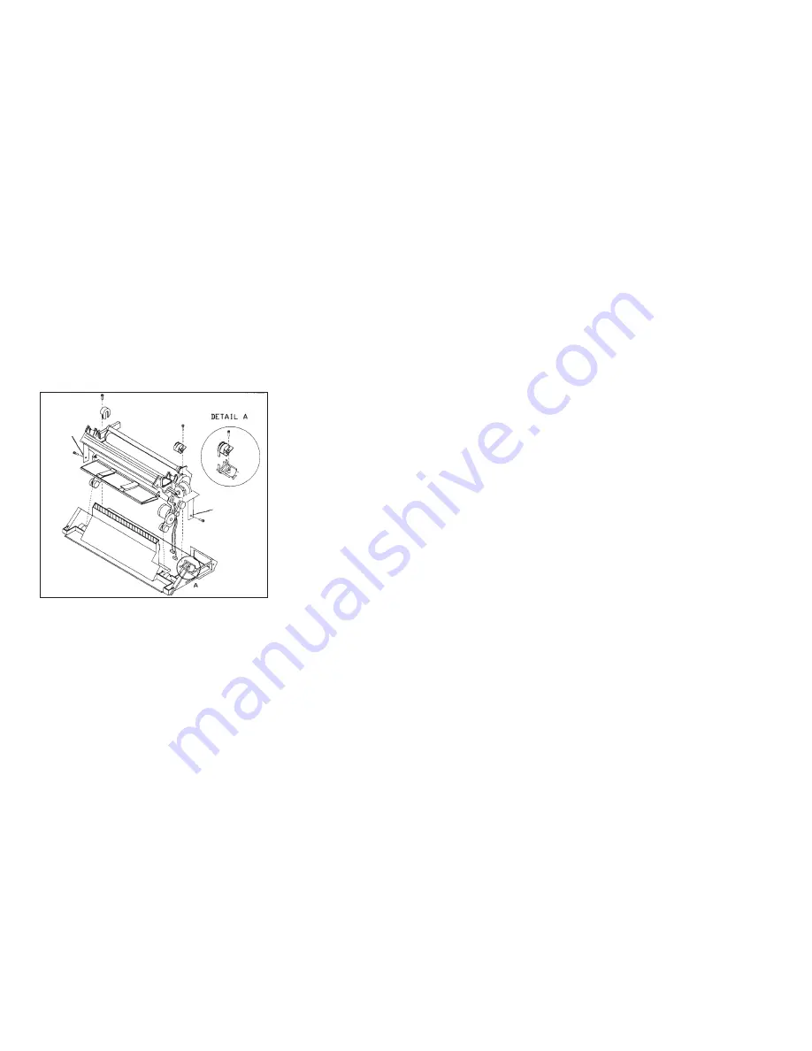
Note: The right side screw can be accessed through the cable slot in the fan mounting bracket, or by
using an offset screwdriver.
c. Remove the 2 wire ties.
Note: The printer mechanical assembly will not come straight up. Pivot it to the front, disengaging the
rubber grommets, and then lift it out.
Replacement
Follow the removal steps in reverse order.
Attention: Do not pinch the cables during installation.
Ground
Ground
Figure 181. Printer Mechanical Assembly
Chapter 5. Removals and Adjustments
446
Summary of Contents for 4247
Page 1: ...4247 Printers Maintenance Information Document Number SA24 4400 05 Part Number 27P8450 IBM ...
Page 241: ...e90apc15 Figure 24 Main Input Power Supply Ground Chapter 3 Circuit Diagrams 241 ...
Page 257: ...Figure 32 Stacker Motor Wiring Chapter 3 Circuit Diagrams 257 ...
Page 261: ...Stacker Cable Wiring Figure 36 Tractor Assembly Cable Wiring Chapter 3 Circuit Diagrams 261 ...


