background image

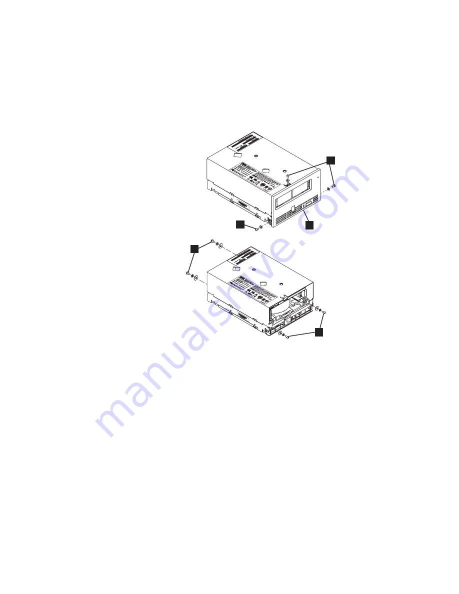
a.


Using


a


Phillips


screwdriver,


remove


the


three


screws


and


washers


1


that


secure


the


bezel


2


to


the


internal


drive,


then


remove


the


bezel.


b.


Remove


the


cover


of


the


internal


drive


by


performing


the


following


steps:


1)


Remove


the


four


cover-mounting


screws


and


washers


3

.


2)


Remove


the


cover


by


lifting


it


up.


__


Step


5.


Inspect


the


drive


to


decide


which


of


the


following


conditions


most


closely


matches


the


symptom


on


the


drive:


v


Tape


spooled


off


the


supply


reel


-


All


the


tape


appears


to


be


on


the


take


up


reel


and


no


tape


is


on


the


supply


reel


(inside


the


cartridge).


Test


the


drive


after


the


procedure


is


completed.


v


Tape


pulled


from


leader


pin


(or


broken


at


the


front


end)


-


All


the


tape


appears


to


be


on


the


supply


reel


(inside


the


cartridge)


and


very


little


or


no


tape


appears


to


be


on


the


take


up


reel.


The


leader


block


is


positioned


in


the


take


up


reel.


Return


the


drive


after


the


procedure


is


completed.


v


Tape


broken


in


mid-tape


-


Tape


appears


to


be


on


both


the


supply


reel


(inside


the


cartridge)


and


take


up


reel.


Test


the


drive


after


the


procedure


is


completed.


v


Tape


tangled


along


tape


path


-


Tape


appears


to


be


tangled


and


damaged


but


in


tact.


Return


the


drive


after


the


procedure


is


completed.


--


OR


--


3

2

1

1

3

a82ru007


Figure


19.


Removing


the


cover


from


the


internal


drive


54


IBM


400/800GB


LTO3


Tape


Drive


User’s


Guide

Summary of Contents for 39M5657

Page 1: ...IBM 400 800GB LTO3 Tape Drive User s Guide...

Page 2: ......

Page 3: ...IBM 400 800GB LTO3 Tape Drive User s Guide...

Page 4: ...e Head on page 14 Updating Firmware on page 26 and Using Ultrium Media on page 31 sections as periodic maintenance is not covered by the IBM warranty Repairs or exchanges resulting from improper maint...

Page 5: ...ion Code 2 Update Drive Firmware from FMR Tape 17 Function Code 3 Create FMR Tape 18 Function Code 4 Force a Drive Dump 18 Function Code 5 Copy Drive Dump 19 Function Code 6 Run SCSI Wrap Test 20 Func...

Page 6: ...Limited Warranty Z125 4753 08 04 2004 73 Part 1 General Terms 73 Part 2 Country unique Terms 76 Part 3 Warranty Information 87 Warranty Period 87 Types of Warranty Service 87 Worldwide telephone list...

Page 7: ...a Safety Information Avant d installer ce produit lisez les consignes de s curit Vor der Installation dieses Produkts die Sicherheitshinweise lesen Prima di installare questo prodotto leggere le Infor...

Page 8: ...L s s kerhetsinformationen innan du installerar den h r produkten...

Page 9: ...adapter or other object Doing so can stress the cord in ways that can cause the cord to fray crack or crimp This can present a safety hazard Always route power cords so that they will not be walked o...

Page 10: ...ower outlet you are using is properly wired easily accessible and located close to the equipment Do not fully extend power cords in a way that will stress the cords Connect and disconnect the equipmen...

Page 11: ...ments v Ventilation slots fans and or heat sinks are provided with the product for safety comfort and reliable operation These features might inadvertently become blocked by placing the product on a b...

Page 12: ...x IBM 400 800GB LTO3 Tape Drive User s Guide...

Page 13: ...potentially hazardous to people because of some existing condition A caution notice can be accompanied by one of several symbols If the symbol is It means A hazardous electrical condition with less se...

Page 14: ...lations at the time of disposal This unit contains recyclable materials The materials should be recycled where facilities are available and according to local regulations Some areas may provide a prod...

Page 15: ...rt that analyzes when the drive requires maintenance v Servicing the Drive on page 52 gives instructions on servicing the drive v Appendix A TapeAlert Flags on page 65 lists TapeAlert messages that ar...

Page 16: ...xiv IBM 400 800GB LTO3 Tape Drive User s Guide...

Page 17: ...r precision head alignment to help support higher track density with improved data integrity and backwards compatibility with previous LTO generations v Graceful dynamic braking designed to maintain t...

Page 18: ...Drive Figure 2 shows the front panel of the drive 1 Status Light 3 Single character Display SCD 2 Unload Button 4 SCD Dot a82ru001 1 2 3 4 Figure 2 Front panel of the drive 2 IBM 400 800GB LTO3 Tape...

Page 19: ...ond MB s If the server s net compressed data rate is between two of the preceding native data rates the drive calculates the appropriate data rate at which to operate Speed matching dramatically reduc...

Page 20: ...rface The drive contains a high density 68 pin D shell receptacle connector HD68 for attachment to the server The HD68 connector includes the connectors for the SCSI signal the SCSI ID and the drive s...

Page 21: ...urface and place the drive on the packaging v Do not place the drive on the cover of the enclosure or on any other metal surface The steps that follow describe how to install the drive into an enclosu...

Page 22: ...powering it on for 30 minutes Use a diagnostic tape to test the drive before inserting a tape that contains data v If the drive is hotter than its operating environment the tape can stick to the drive...

Page 23: ...f needle nose pliers to connect the jumpers to the pins that are shaded Note If you set the SCSI ID to 15 the drive will not necessarily be set to that ID instead the drive will expect to receive the...

Page 24: ...aces the tape load compartment of the enclosure __ 3 Insert two M3 screws into the mounting holes 2 of the two side brackets located on the left and right sides of the chassis Attention When inserted...

Page 25: ...ensure that the drive is receiving power watch for the following while turning on the power to the host v The SCD presents a series of random characters then becomes blank not lit Attention If the SC...

Page 26: ...e enclosure and the server for the location of the connectors refer to the documentation for your enclosure and server __ 2 Run the appropriate SCSI attachment verification procedure from your server...

Page 27: ...is blank during normal operation SCD Dot If a drive dump is present while the drive is in maintenance mode a single red dot illuminates in the lower right corner of the SCD 8 To copy the dump see Fun...

Page 28: ...hile in maintenance mode Flashing Amber once per second Displaying error code An error occurred and the drive or media may require service or it may require cleaning Note the code on the SCD then go t...

Page 29: ...blank Force a drive dump part of the maintenance mode Attention If the drive detects a permanent error and displays an error code it automatically forces a drive dump also known as a save of the firmw...

Page 30: ...dge partially ejects grasp the cartridge and remove it Whenever you unload a tape cartridge the drive writes any pertinent information to the cartridge memory Mid tape Recovery If a power cycle or res...

Page 31: ...ic and maintenance functions The drive must be in maintenance mode to perform these functions Attention Maintenance functions cannot be performed concurrently with read or write operations While in ma...

Page 32: ...r the drive can properly load and unload cartridges and read and write data The diagnostic loops ten times To stop the diagnostic and exit maintenance mode press the Unload Button once to abort the te...

Page 33: ...om pc support site wss document do lndocid TAPE FILES Attention Customers should only attempt this step when requested by IBM service 1 Place the drive in maintenance mode For instructions see Enterin...

Page 34: ...a flashing 3 The tape drive copies the FMR data to the scratch data cartridge Note If you inserted an invalid or write protected tape cartridge error code 7 appears in the SCD The tape drive unloads t...

Page 35: ...he drive in maintenance mode For instructions see Entering Maintenance Mode on page 15 2 Press the Unload Button once per second to cycle through the following functions v 5 0 no function v 5 1 copy d...

Page 36: ...I wrap plug is connected to one of the SCSI connectors at the rear of the drive 4 Make sure that the drive is terminated at one of its SCSI connectors or at the SCSI bus 5 Press and hold the Unload Bu...

Page 37: ...ape This converts the cartridge into a valid scratch blank data cartridge Attention Customers should only attempt this step when requested by IBM service 1 Place the drive in maintenance mode For inst...

Page 38: ...the contents of the error code log 1 Place the drive in maintenance mode For instructions see Entering Maintenance Mode on page 15 2 Press the Unload Button once per second until A appears in the SCD...

Page 39: ...nloads the cartridge and exits maintenance mode v If an error is detected the test stops 6 or 7 appears in the SCD another code could appear To determine the error locate 6 or 7 in Table 9 on page 45...

Page 40: ...xits maintenance mode To clear the error turn the power off then on again Function Code H Test Head Approximate Run Time 10 minutes Total Number of Loops 10 Function Code H performs tests to ensure th...

Page 41: ...h cartridge for this test 1 Place the drive in maintenance mode For instructions see Entering Maintenance Mode on page 15 2 Press the Unload Button once per second until L appears in the SCD If you cy...

Page 42: ...tton for three seconds while P appears in the SCD The SCD changes to U then exits maintenance mode Updating Firmware Attention When updating firmware do not power off the drive until the update is com...

Page 43: ...p retrievals can be performed by the tool as well Currently the tool is very similar to the LTO TDX drive only firmware update and drive dump retrieval tool explained in detail later on in the Tape Dr...

Page 44: ...executable file is copied to another location where the firmware or dump folders do not exist The tool will detect the missing folders at launch and present the user license assuming that this is the...

Page 45: ...progress 7 A Wait message is displayed on the user screen during firmware load 8 If the program tries to load code and it fails with a sense Key 5 and an ASC ASCQ of 82 83 the following wording is di...

Page 46: ...ds When C flashes the drive is waiting for a cartridge 4 Insert the FMR tape cartridge 8 flashes the drive loads the updated firmware from the cartridge and the Status Light flashes amber When the upd...

Page 47: ...ct Switch 2 Cartridge door 5 Label area 3 Leader Pin 6 Insertion guide Cartridge Compatibility Table 3 Ultrium data and cleaning cartridge compatibility with Ultrium tape drive Tape Drive LTO Ultrium...

Page 48: ...oor the tape is attached to a leader pin 3 When the cartridge is inserted into the drive a threading mechanism pulls the pin and tape out of the cartridge across the drive head and onto a non removabl...

Page 49: ...icates that the cartridge is the third generation of its type Figure 9 shows a sample bar code label for the LTO Ultrium Tape Cartridge Tape cartridges can be ordered with the labels included or with...

Page 50: ...flat to within 0 5 mm 0 02 in over the length of the label and have no folds missing pieces or smudges v Do not place other machine readable labels on other surfaces of the cartridge They may interfer...

Page 51: ...e Repositioning a Leader Pin A leader pin that is improperly seated inside a cartridge can interfere with the operation of the drive Figure 11 shows a leader pin in the incorrect 1 and correct 2 posit...

Page 52: ...e s hub 2 and turn it clockwise until the tape becomes taut 6 Remove the rewind tool by pulling it away from the cartridge 7 If you suspect that the cartridge has been mishandled but it appears useabl...

Page 53: ...Leader pins and C clips Attention v Use only the IBM Leader Pin Reattachment Kit to reattach the leader pin to the tape Other methods of reattaching the pin will damage the tape the drive or both v Us...

Page 54: ...e cartridge 2 so that the tool s hook 3 latches into the cartridge s door 4 Pull the tool back to hold the door open then slide the tool onto the cartridge Open the tool s pivot arm 5 Figure 15 Attach...

Page 55: ...ind it from the cartridge 4 Remove the rewind tool by pulling it away from the cartridge Set the tool and the cartridge aside 5 On the leader pin 1 locate the open side of the C clip 2 The C clip is a...

Page 56: ...Use care to ensure that the tape is centered over the leader pin Failure to properly center the tape on the pin will cause the repaired cartridge to fail When the tape is properly centered a 0 25 mm 0...

Page 57: ...sentative for information about the materials that are in the cartridge If a tape cartridge must be disposed of in a secure manner you can erase the data on the cartridge by using a high energy ac deg...

Page 58: ...der the cartridge from any authorized IBM Business Partner or your IBM Sales Representative by specifying Machine Type 3589 Model 002 Specify the VOLSER characters that you want IBM TotalStorage LTO U...

Page 59: ...datawarelabels com Dataware Labels Europe Heubergstrasse 9 D 83052 Bruckmuhl Gotting Germany Telephone 49 8062 9455 http www datawarelabels com NetC P O Box 1067 Fairfield CT 06825 U S A Telephone 20...

Page 60: ...65 The server reported SCSI problems such as selection or command time outs or parity errors See Fixing SCSI Bus Errors on page 50 The library reported an LDI or RS 422 communication problem with the...

Page 61: ...A drive dump will be created Error Code Cause and Action 0 No error occurred and no action is required This code displays v When power is cycled turned off then on to the tape drive v When diagnostics...

Page 62: ...re or tape drive hardware failure occurred Perform the following action 1 Collect a drive dump from one of the following Note Do not force a new dump one already exists v Server s SCSI interface by us...

Page 63: ...cartridge s volume serial number run Function Code 1 Run Drive Diagnostics on page 16 v If the diagnostics fail replace the tape drive v If the diagnostics succeed run Function Code H Test Head on pa...

Page 64: ...e in maintenance mode 8 Tape drive or SCSI bus failure The tape drive determined that a failure occurred in the tape drive s hardware or in the SCSI bus The error code clears 10 seconds after the driv...

Page 65: ...ermine where to send the file for analysis contact your Product Application Engineer PAE Using a Device Driver Utility To obtain a drive dump by using a device driver utility determine whether your se...

Page 66: ...the test fails replace the SCSI terminator first then the SCSI cable and the interposer if installed Repeat the operation that caused the error If you replaced the SCSI terminator or SCSI cable and t...

Page 67: ...xing an Intermittent Error with a Single Drive on a SCSI Bus 1 Replace the SCSI terminator on the drive 2 Run the operation that caused the error If the problem persists the problem may be with the ca...

Page 68: ...following procedure Attention When you run the Test Cartridge Media diagnostic data on the suspect tape is overwritten Use only a scratch data cartridge to run the test 1 If possible run the tape cart...

Page 69: ...o perform this procedure v To avoid contamination and electrostatic discharge damage to the drive never touch the head or electronic components inside the drive v If you cannot remove the cartridge fr...

Page 70: ...rtridge Test the drive after the procedure is completed v Tape pulled from leader pin or broken at the front end All the tape appears to be on the supply reel inside the cartridge and very little or n...

Page 71: ...it onto the supply reel inside the cartridge __ Step 5 From the bottom of the drive insert a 2 5 mm offset hex wrench through the bottom cover access hole and into the reel motor axle __ Step 6 Turn t...

Page 72: ...up reel go to Tape Broken in Mid tape on page 57 __ Step 2 If there is less than approximately 0 6 m 2 ft of tape on the take up reel cut off the excess tape as close to the leader pin as possible __...

Page 73: ...otor worm gear 4 to turn the threader mechanism gear 6 counterclockwise This moves the LBA out of the cartridge and past the read write head Stop this rotation when the LBA is near the tape guide roll...

Page 74: ...o the cartridge by turning the hex wrench clockwise __ Step 7 Turn the supply reel clockwise carefully guiding the mended portion of the tape to wind around the hub of the supply reel located inside t...

Page 75: ...rench through the bottom cover access hole and into the reel motor axle Begin spooling the tape back into the cartridge by turning the hex wrench clockwise __ Step 5 Continue spooling into the cartrid...

Page 76: ...s click into place If you do not hear the click continue rolling until the threader motor worm gear 4 stops The LBA is in the correct position Note Be sure to keep tension on the tape as the LBA is dr...

Page 77: ...ive shown as 1 __ Step 11 Continue rotating the loader motor worm gear 1 until the rotator stub 3 is positioned as shown Notice that the rotator stub 3 is nearly aligned with the cartridge loader tray...

Page 78: ...ges of the tape guiding rollers Ensure that you do not stretch the tape __ Step 5 Locate the threader motor worm gear 4 on the rear of the drive You can either a Use your finger to rotate the threader...

Page 79: ...sition Note Be sure to keep tension on the tape as the LBA is drawn into the cartridge by using a hex wrench __ Step 7 Notice the a Loader mechanism gear 6 nearest the front of the drive that actuates...

Page 80: ...tor worm gear 1 until the rotator stub 3 is positioned as shown Notice that the rotator stub 3 is nearly aligned with the cartridge loader tray guide bearing 2 __ Step 11 Remove the cartridge from the...

Page 81: ...idge If Flag 4 is not set see error code 6 in Table 9 on page 45 6 06h Write failure Set for any unrecoverable write or positioning error where isolation is uncertain and failure could be due to a fau...

Page 82: ...he drive expects a cleaning cartridge and the loaded cartridge is not a cleaning cartridge Use a valid cleaning cartridge 30 1Eh Hardware A Set when a hardware failure occurs which requires that you r...

Page 83: ...error code 6 in Error Codes and Messages on page 45 51 33h Tape directory invalid at unload Set when the tape directory on the tape cartridge that was previously unloaded is corrupted The file search...

Page 84: ...68 IBM 400 800GB LTO3 Tape Drive User s Guide...

Page 85: ...Supply Current steady state 1 3 A 0 2 A Maximum Supply Current steady state 3 0 A 1 1 A Peak Supply Current instantaneous power by power supply 3 3 A for 100 ms 15 W 4 50 A for 2 ms 49 20 W Power Mea...

Page 86: ...Other Specifications Maximum altitude 3048 m 10 000 ft for operating and storage 12192 m 40 000 ft for shipping Extraction force 250 to 750 gms force 70 IBM 400 800GB LTO3 Tape Drive User s Guide...

Page 87: ...wn from marketing Additional support offerings including step by step installation assistance are available for a nominal fee To assist the technical support representative have available as much of t...

Page 88: ...72 IBM 400 800GB LTO3 Tape Drive User s Guide...

Page 89: ...es a removed part will assume the warranty service status of the removed part Unless IBM specifies otherwise these warranties apply only in the country or region in which you purchased the Machine THE...

Page 90: ...your problem can be resolved with a Customer Replaceable Unit CRU e g keyboard mouse speaker memory hard disk drive IBM will ship the CRU to you for you to install If the Machine does not function as...

Page 91: ...turn to IBM for any reason You should remove all such information from the Machine prior to its return Circumstances may arise where because of a default on IBM s part or other liability you are entit...

Page 92: ...n The following is added after the first sentence Any litigation arising from this Statement of Limited Warranty will be settled exclusively by the courts of the city of La Paz BRAZIL Jurisdiction The...

Page 93: ...e City of Caracas NORTH AMERICA How to Obtain Warranty Service The following is added to this Section To obtain warranty service from IBM in Canada or the United States call 1 800 IBM SERV 426 7378 CA...

Page 94: ...ceedings Vacancies in the post of chairman shall be filled by the president of the SIAC Other vacancies shall be filled by the respective nominating party Proceedings shall continue from the stage the...

Page 95: ...ersion of this Statement of Limited Warranty prevails over any other language version JAPAN Governing Law The following sentence is added to this Section Any doubts concerning this Statement of Limite...

Page 96: ...l be conducted including all documents presented in such proceedings in the English language The English language version of this Statement of Limited Warranty prevails over any other language version...

Page 97: ...a Vanuatu and Wallis Futuna 3 the laws of Finland in Estonia Latvia and Lithuania 4 the laws of England in Angola Bahrain Botswana Burundi Egypt Eritrea Ethiopia Ghana Jordan Kenya Kuwait Liberia Mala...

Page 98: ...of this Statement of Limited Warranty or related to its violation termination or nullity will be finally settled under the Rules of Arbitration and Conciliation of the International Arbitral Center o...

Page 99: ...MAGES OR FOR ANY ECONOMIC CONSEQUENTIAL DAMAGES 3 LOST PROFITS EVEN IF THEY ARISE AS AN IMMEDIATE CONSEQUENCE OF THE EVENT THAT GENERATED THE DAMAGES OR 4 LOSS OF BUSINESS REVENUE GOODWILL OR ANTICIPA...

Page 100: ...damages caused by IBM with fraud or gross negligence and for express warranty The following sentence is added to the end of item 2 IBM s liability under this item is limited to the violation of essen...

Page 101: ...f the present Statement of Limited Warranty balance this limitation of liability IRELAND What this Warranty Covers The following is added to this section Except as expressly provided in these terms an...

Page 102: ...s of this section a Default means any act statement omission or negligence on the part of IBM in connection with or in relation to the subject matter of this Statement of Limited Warranty in respect o...

Page 103: ...ce may be provided by your reseller if approved by IBM to perform warranty service Scheduling of service will depend upon the time of your call and is subject to parts availability Service levels are...

Page 104: ...responsible for the subsequent installation and verification of the Machine 5 CRU and On site Service This type of Warranty Service is a combination of Type 1 and Type 2 see above 6 CRU and Courier o...

Page 105: ...me Brazil Portuguese 55 11 3889 8986 8AM 6PM Monday Friday Local time Canada English French 1 800 565 3344 1 800 565 3344 In Toronto only call 416 383 3344 24 hours day 7 days week Chile Spanish 800 2...

Page 106: ...ance French 33 238 557 450 9AM 6PM Monday Friday Local time Germany German 49 7032 15 49201 9AM 5 30PM Monday Friday Local time Greece 30 210 680 1700 Guatemala Spanish 335 8490 8AM 5PM Monday Friday...

Page 107: ...y of the month Year end Japanese IntelliStation and xSeries Inside Japan and Overseas calls 81 46 266 1358 IntelliStation and xSeries 9AM 5PM Monday Friday Except Saturday Sunday Holidays Year End Jap...

Page 108: ...y Local time Russian Federation Russian 7 095 940 2000 Singapore English 1800 3172 888 8AM 6 30PM Monday Friday Local time Slovakia 421 2 4954 1217 Slovenia 386 1 5830 050 Spain Spanish 34 91 714 7983...

Page 109: ...day 7 days week Uruguay Spanish 000 411 005 6649 9AM 10PM Monday Friday Local time Venezuela Spanish 0 800 100 2011 8AM 9PM Monday Friday Local time Vietnam English Vietnamese Ho Chi Minh 848 824 147...

Page 110: ...94 IBM 400 800GB LTO3 Tape Drive User s Guide...

Page 111: ...80 where you will be directed to the nearest Authorized Service Center Should no Authorized Service Center exist in your city location or within 70 kilometers of your city or location the guarantee in...

Page 112: ...96 IBM 400 800GB LTO3 Tape Drive User s Guide...

Page 113: ...ormation could include technical inaccuracies or typographical errors Changes are periodically made to the information herein these changes will be incorporated in new editions of the publication IBM...

Page 114: ...cations Operation of this equipment in a residential area is likely to cause harmful interference in which case the user will be required to correct the interference at his own expense Properly shield...

Page 115: ...echtigt in bereinstimmung mit dem Deutschen EMVG das EG Konformit tszeichen CE zu f hren Verantwortlich f r die Konformit tserkl rung nach Paragraf 5 des EMVG ist die IBM Deutschland GmbH 70548 Stuttg...

Page 116: ...a Classe A ai sensi del CISPR 22 Norma Europea EN 55022 I limiti delle apparecchiature della Classe A sono stati stabiliti al fine di fornire ragionevole protezione da interferenze mediante dispositiv...

Page 117: ...Notices 101...

Page 118: ...102 IBM 400 800GB LTO3 Tape Drive User s Guide...

Page 119: ......

Page 120: ...Part Number 25R0021 Printed in USA 1P P N 25R0021...

Reviews: