background image

www.ismacontrolli.com

page 6

DBL394en | 1

st

 Issue rev. 8 | 07/2022

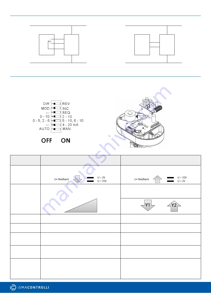
WIRING DIAGRAMS

3 point floating control

Modulating control (0-10 V DC)

230 V AC

3-point Floating Control

Controller

Open
Close

MVE

Y2

Y1 F

M

N

Neutral

Modulating Control (0-10Vcc)

230V AC

Controller

C
Command -

MVE

M

Y

F

N

Neutral

DIP SWITCHES SETTINGS

Set the DIP switches according to tables below. Power down and power up again the actuator or act on the manual override handle 

to be sure that settings will be recognized.

Factory settings

DIP SWITCH

OFF

ON

1

Direct Action

Reverse Action

2

Modulating Control (MOD) (Input between Y [+] and 

M [-])

3 point floating (INC) ( Y1 open-extend , Y2 close-re-

tract connected to M)

3

-

Selection of sequence mode, 

control range defined by DIP n. 5

4

Modulating Control 0-10 V DC 

(DIP n. 2 OFF only)

Modulating Control 2-10 V DC 

(DIP n. 2 OFF only)

5

Sequence Control 0-5 V DC with DIP n. 4 OFF only 

Sequence Control 2-6 V DC with DIP n. 4 ON only 

(DIP n. 3 ON only)

Sequence Control 5-10 V DC with DIP n. 4 OFF only 

Sequence Control 6-10 V DC with DIP n. 4 ON only 

(DIP n. 3 ON only)

6

Voltage Input Signal V DC 

(input between Y [+] and M [-])

Current Input Signal 4-20 mA (input between Y [+] 

and M [-]).

 In this case DIP n. 4 must be set to ON.

7

Automatic Calibration: the actuator updates the 

stroke range if an unexpected mechanical stop is 

detected for at least 10 s

Manual Calibration: the actuator calibration is started 

moving the DIP from OFF to ON or vice versa. With 

DIP in ON in case of extra stroke or if an unexpected 

endpoint is detected, the actuator will never update 

the stroke 

Summary of Contents for MVE2 Series

Page 1: ...and it is able to self calibrate on a different stroke without the need of any user action this function is DIP switch selectable on the field MVE2xx has intelligent behaviour and alarm functionality...

Page 2: ...ion until it is raised again then board and motor will be powered again At the end of this operation the actuator moves to initial position on the basis of DIP n 1 setting then it follows the control...

Page 3: ...ng accordingly see Diagnostic Alarm Function Table ASSEMBLING The actuator can be mounted with any orientation but never up side down When the fluid temperature exceed 120 C the actuator shall be moun...

Page 4: ...o H2 X S and H3 X S with AG82 with AG82 Siemens with AG70 10 with AG70 14 Danfoss VR VF S models with AG60 07 TAC DN15 V298 with AG60 08 TAC DN15 V2XX V3XX with AG60 09 Honeywell with AG60 10 Airtek w...

Page 5: ...m Y2 Close V 16 V DC Voltage Output max 25 mA AWG20 min 0 5mm2 max 1 5mm2 200 m M 0 V Common U 2 10 V DC Feedback Output Signal AWG20 min 0 5mm2 max 1 5mm2 200 m M 0 V Common Note To avoid damages to...

Page 6: ...3 Selection of sequence mode control range defined by DIP n 5 4 Modulating Control 0 10 V DC DIP n 2 OFF only Modulating Control 2 10 V DC DIP n 2 OFF only 5 Sequence Control 0 5 V DC with DIP n 4 OF...

Page 7: ...st the new stroke limit then it goes back to the initial position still signalling the anomaly until it is not within 60mm The actua tor does not calibrate the stroke after 10s wrong range Valve with...

Page 8: ...me point of the stroke read 2 GREEN BLINKING The actuator arrived at the intermediate point of the stroke read 3 RED GREEN BLINKING The actuator is reading the stroke or it is going to initial positio...

Reviews: