IAME REEDSTER 125cc Assembly Instructions & User Manual Download Page 27


MAN-051 ING 

25


We will get a richer carburetion by lifting the needle, that is, by moving down the retainer clip to a lower 
notch; and on the contrary, a leaner carburetion is achieved lowering the needle, that is by lifting the retainer 
clip to a higher notch (see fig.3). On the picture is shown the basic needle adjustment.  
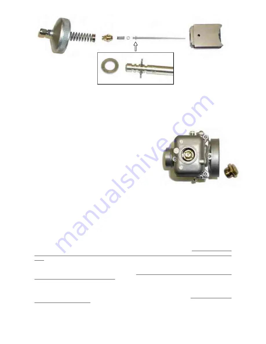
To reach the conical needle proceed as follow: screw out the upper locking ring on the carb., then pull off  
the throttle gas together with the needle, release the throttle cable, and screw out the fixing screw on the 
throttle gas.  
 

The adjustment of the carburetion

 at top RPM  is mainly performed by means of: 


The max. jet 


By increasing the "H" max jet size (see fig.2),   
we get a richer carburetion, and vice versa, a leaner one,  
by decreasing the jet size. 


To reach to the max. Jet, screw out  the central plug on the 
 float chamber (see fig.4), or disassemble the float chamber itself. 
 
As anticipated, there is no clear distinction among the areas 
of influence of the different components, as they interact  
and influence each other.  
As a matter of fact, the  max. jet affects, not only the  
carburetion, at wide open throttle gas, but also the  
whole mid range carburetion, even if  less sensibly vs. the needle position;  
indirectly, the needle position slightly influences the carburetion, at completely opened throttle. 
In the same way, when the throttle is slightly opened, the effects of the min. jet and the air screw 
superimpose with the effect of the conical needle position. 


To properly adjust the carburetion according to the ambient conditions, we are giving some indicative 
parameters, to adapt the max. jet  size as a function of the variation of the ambient temperature and the 
altitude at which  the engine is operating. 
As you know, carburetion, that is, the exact quantity of fuel to be mixed to a given quantity of air, is 
influenced by atmospheric factors, such as temperature and pressure. The more the temperature drops, the 
more  the air density increases and consequently, there will be more molecules of gas in the same volume. 
As the carb. mixes always the same fuel quantity this would be insufficient and the carb. will provide a leaner 
mixture. In these conditions, as you are aware, when operating with a leaner mixture, the engine runs the 
following risks: overheating, insufficient lubrication, detonation, seizure; for this reason the carburettor setting 
must be adjusted by increasing the max. jet size by about 2-3 points for every 6°C  external temperature 
drop.  
Of course, on the contrary, the more the temperature rises, the more the carburetion becomes richer and 
gives origin to less critical consequences than the ones experienced with a leaner carburetion. So, also in 
this case, it is suggested to optimize the carb. setting , by decreasing the max. jet size by about  2-3 points 
for every 6°C external temperature increase. 
The variation of the atmospheric pressure, which is significant  when varying the altitude at which the engine 
is operating, gives origin to such a phenomenon; by decreasing the altitude, the atmospheric pressure 
increases, consequently in the same air volume sucked by the engine, more molecules of gas are present 
Therefore, in this case too, a carb. adjustment is required;  increase the  max. jet size by about 2-3 points for 
every  350m altitude decrease. 


Fig.3 

Fig.4 

Summary of Contents for REEDSTER 125cc

Page 1: ...MAN 051 ING ASSEMBLY INSTRUCTIONS USER MANUAL 09 03 07 REEDSTER 125cc F1 F2 F3 F4 Versions...

Page 2: ...s 2 10 Install the intake silencer 2 11 Install the exhaust Section 3 USE OF THE ENGINE 3 1 Charging discharging the oil in the gear box 3 2 Gasoline and oil 3 3 Carburettor adjustment guide 3 4 Start...

Page 3: ...earings It is of steel alloy hardened and tempered as is the connecting rod which is machined from the full The rod runs on roller bearings on both ends The crankcase houses a balance shaft driven by...

Page 4: ...nly F3 and F4 is supplied with a kit which includes the homologated radiator the water hoses the thermostat and the fixing supports on the chassis 1 2 CHARACTERISTICS OF THE ENGINE OPERATION LIMITS Th...

Page 5: ...HSH30 CS carburettor 1 only F4 Fuel pump 1 only F4 Inlet silencer 1 only F4 ELECTRICAL SYSTEM Battery 12 V 1 Battery support 1 Battery strip 1 Battery fixing clamps 2 Electronic box 1 Starting relay 1...

Page 6: ...4 1 4 ACCESSORIES EXHAUST SYSTEM BATTERY WITH SUPPORT COMPLETE ELECTRIC SYSTEM CLUTCH COVER H T COIL INLET SILENCER CARBURETTOR RADIATOR RADIATOR SUPPORT KIT WATER HOSES KIT THERMOSTAT NGK SPARK PLUG...

Page 7: ...normally includes a letter followed by 4 digits there can be exceptions in some special cases Other numbers stamped on the crankcase or on other surfaces of the motor refer to various manufacturing pr...

Page 8: ...assis it is at care of the assembler to follow these instructions The final customer in this case can skip this section and can start reading from section 3 Whenever the engine or a component is disas...

Page 9: ...NSTALL THE 4 RUBBER DAMPENERS IN THE RADIATOR FIXING HOLES SEE FIG 1 2 PLACE THE RADIATOR SUPPORT BRACKET BETWEEN THE RADIATOR FIXINGS BY TILTING ONE END AND INSERTING IT THROUGH THE RUBBER DAMPENERS...

Page 10: ...NUT INSTALL THE Z SHAPE BRACKET ON THE RADIATOR SUPPORT BRACKET TONGUE N 1 SCREW M8X45 WITH NUT DO NOT TIGHTEN THE SCREW SEE FIG 5 4 FIX THE RADIATOR Z SHAPE LOWER BRACKET ON THE CHASSIS RAIL FIXING B...

Page 11: ...ING AND THE T FITTING CONNECT THE 5 HOSE BETWEEN THE ENGINE OUTLET AND THE THERMOSTAT INLET FASTEN WITH STEEL CLAMPS ALL THE HOSE ENDS 7 THE THERMOSTAT MUST BE POSITIONED SO THAT THE REAR UNION FOR TH...

Page 12: ...DY PRE INSTALLED 2 3 2 WHEN THE SHIPMENT IS MADE THE ENGINE INNER PARTS ARE PROTECTED BY PLASTIC PLUGS WHICH MUST BE REMOVED BEFORE INSTALLING THE ENGINE SEE FIG 2 SPARK PLUG HOLE PLUG WATER FITTING P...

Page 13: ...IFOLD ATTENTON MAKE SURE THAT THE PRESSURE HOLE ON THE GASKET IS NOT PLUGGED 2 5 2 INSTALL THE CARBURETTOR N 2 NUTS M6 TORQUE AT A 6 10 Nm 50 90 in lb SEE FIG 5 HEXAGONAL WRENCH 5 mm ATTENTION WHEN RE...

Page 14: ...SELF LOCKING NUTS M6 TORQUE AT 6 10 Nm 50 90 in lb SEE FIG 7 10mm PIPE WRENCH 2 5 4 INSTALLATION OF THE CARBURETTOR REMOVE THE PLASTIC PLUG FROM THE INLET MANIFOLD AND INSTALL THE CARB THEN TIGHTEN T...

Page 15: ...E THE OIL LEVEL PLUG FRONT PART OF THE ENGINE SEE FIG 11 HEXAGONAL WRENCH 4mm 2 6 2 FILL WITH 33cc IAME EP100 OIL THE GEAR BOX SEE FIG 12 NOTE IF THE LEVEL IS CORRECT YOU WILL SEE A LIGHT OUTCOME OF O...

Page 16: ...IS NOT INSTALLED AND PROPERLY ALIGNED 2 7 2 CHECK THE ALIGNMENT OF THE ENGINE SPROCKET AND THE AXLE SPROCKET WITH A STRAIGHT EDGE SEE FIG 14 2 7 3 INSTALL THE CHAIN PITCH 7 775 SEE FIG 15 2 7 4 MOVE...

Page 17: ...AKE SURE THAT THE COPPER GROUND CABLE ALWAYS CONNECTS THE H T COIL WITH THE ENGINE AN INADEQUATE GROUNDING COULD DAMAGE THE IGNITION SYSTEM BEYOND REPAIR THE POSITION OF THE H T COIL HAS BEEN CHOSEN T...

Page 18: ...HE BOX WITH MORE THAN ONE BOLT DEPENDING ON THE TYPE OF CHASSIS NOTE THE BOX AND CLAMPS ARE PROVIDED WITH VARIOUS HOLES TO ALLOW INSTALLATION ON ALL KIND OF CHASSIS 2 9 3 INSERT THE BATTERY IN THE BOX...

Page 19: ...ECK THAT THE PLASTIC CLAMP FASTENS THE CABLE FROM THE ELECTRIC STARTER TO THE STARTER BODY SEE FIG 25 ATTENTION THIS OPERATION IS VERY IMPORTANT OTHERWISE THE RESIDUAL ENGINE VIBRATIONS COULD DAMAGE T...

Page 20: ...ER FUSE AND THE RELAY SEE FIG 29 NOTE THE COLOUR OF THE ELECTRONIC BOX CHANGES ACCORDING TO THE ENGINE VERSION AND TO THE REV LIMITER SETTING YELLOW F4 vers 14000 RPM max BLUE F3 vers 14000 RPM max GR...

Page 21: ...ESS SEE FIG 33 ATTENTION MAKE SURE THAT THE FIXING TONGUE OF THE CONNECTOR IS PROPERLY INSERTED TO GUARANTEE THE BEST POSSIBLE CONNECTION OF THE TERMINALS 2 9 14 ATTACH THE DUAL LOCK STRAP UNDER THE F...

Page 22: ...KS OF THE JUNCTION BLOCK SEE FIG 36 2 9 17 PLACE THE BATTERY TERMINALS OF THE HARNESS UNDER THE STRAP SEE FIG 37 SUGGESTION NEVER CONNECT THE BATTERY UNTIL YOU ARE READY TO START THE ENGINE SEAL THE B...

Page 23: ...AKE SILENCER 2 10 MAKE SURE THAT THE FILTER HAS THE INLET HOLES TOWARDS THE UPPER SIDE SEE FIG 40 AND THAT THEY ARE NOT PLUGGED TIGHTEN THE CLAMP ON THE CARB AND FIX THE FILTER TO THE CHASSIS SIDE RAI...

Page 24: ...erwise top up discharge the oil Unscrew the oil level plug n 3 on the picture and loosen the oil drain plug to let air in the gearbox 3 2 GASOLINE AND OIL Use leaded super or unleaded green gasoline m...

Page 25: ...urettor H 0 20 20 L 1 30 1 turn and 30 Based on various factors as altitude ambient temperature etc it might be necessary to reset the carb setting to optimize the performance of the engine ATTENTION...

Page 26: ...M can be adjusted by means of the A screw see fig 1 which intervenes on the throttle valve by slightly lifting or and lowering it It is necessary to turn clockwise to increase the RPM and turn counter...

Page 27: ...we are giving some indicative parameters to adapt the max jet size as a function of the variation of the ambient temperature and the altitude at which the engine is operating As you know carburetion t...

Page 28: ...clusively connected to the fuel feeding The fuel feeding is regulated by the floater valve system located in the float chamber In case impurities particles are present in the fuel these might prevent...

Page 29: ...s A Turn the key to RUN position this connects the battery B Turn the key to START position to start the engine the electric starter is immediately disengaged when turning the key to RUN position or w...

Page 30: ...d check the torque of the exhaust header nuts as during the break in the nuts tend to become loose refer to the attached table 3 6 RPM LIMITATION The electronic box integrates an RPM limiter which pre...

Page 31: ...n general by shortening the total length an improvement at high RPM is achieved and vice versa by lengthening it the low RPM is improved When testing though never exceed in lengthening or shortening b...

Page 32: ...ment ring nut on the power valve one notch at a time until the phenomenon disappears If the power valve opens too late that is over 9500 RPM the driver will feel a power output discontinuity above thi...

Page 33: ...before use ATTENTION Always connect the negative terminal before and the pole positive terminal after Always disconnect the battery in opposite order Recharge the battery at least once every 6 months...

Page 34: ...ly in contact with the lamination pack on the H T coil 8 Never use H T coils different than the original coil on the engine Use of a different coil may cause damages to the electronic box 9 The digita...

Page 35: ...e the same final look which can also be achieved with a hot or cold spark plug See table An excessive warm spark plug shows the symptoms listed aside ATTENTION Always use a warmer than standard spark...

Page 36: ...75 mm but 11 and 13 teeth sprockets are available as accessories Table 1 shows the various ratios between the sprocket on the axle and the engine sprocket given the different axle and engine sprockets...

Page 37: ...d Make a few laps on the track and let us assume that you read a max of 12500 engine RPM From table 2 to achieve a max RPM of 13500 operating limit for F4 engine version a sprocket ratio from 7 08 and...

Page 38: ...MAN 051 ING 36 SPROCKET RATIO TO ACHIEVE MAX 14500 RPM F2 Sprocket ratio Max engine RPM during tests SPROCKET RATIO TO ACHIEVE MAX 15500 RPM F1 Sprocket ratio Max engine RPM during tests...

Page 39: ...accident stop the engine immediately and degrease the clutch drum and hub with specific solvents Check the sprocket status after each race or test and replace if necessary A bad alignment of the sproc...

Page 40: ...ankshaft from turning Piston fitting P N 10271 3 Remove nut 1 screw M10x1 12 point wrench 17 mm 4 Remove the external washer the drum complete with roller cage the internal washer 5 Remove the special...

Page 41: ...Locking tool P N S884 Allen wrench 30 mm torque at 100 120 Nm 4 Install inner washer ATTENTION install washer with bevel towards the crankshaft Clean the roller cage and grease it before installing it...

Page 42: ...cables and coil Check status and connectors Engine mounts and clamps Check torques After use Battery disconnect Chain Oil chain Engine External cleaning Every 4 hrs Piston Replace Bendix assembly Remo...

Page 43: ...pipe Replace gaskets and membranes on carburettor Check reed petals Replace if necessary Engine starts but it stops after a few seconds when turning the key in RUN position Bad cable connection Check...

Page 44: ...be preserved as follows Disconnect battery and recharge it periodically see sect 3 10 Disconnect carburettor and clean it Seal with tape the engine inlet and exhaust The external of the engine must be...

Page 45: ...MAN 051 ING 43...

Reviews: