14
115
4.5
105
10
2.1
φ
5
5
14.5
45
10
φ
5
105
5
4.5
2.1
30
123
12.5
12.5
5
4
11
5
10
5
(6
.5
)
6.5
6.5
35
2
35
.4
(
35
m
m
D
IN
レール幅
)
DI
N
レール中心か
ら
66
.5
(Reference) Selection of Power Supply Protection Circuit Breaker
It is recommended that the power supply protection is conducted on the primary side (AC power side) of the 24V DC power
supply unit. When selecting the protection breaker, consider the rated cutoff current of the circuit breaker so a cutoff is surely
performed even in the case of inrush current of 24V DC power supply unit or a short-circuit of the power supply.
• Rated Breaking Current > Short-circuit Current = Primary Power Supply Capacity / Power Voltage
• (Reference) In-rush Current of IAI Power Supply Unit PS241 = 50 to 60A, 3msec
● DeviceNet Interface
Item
Specification
DeviceNet2.0
Group 2 dedicated server
Communication Protocol
Network-powered insulation node
Baud Rate
Automatically follows the master
Communication System
Master-slave system (Polling)
Number of Occupied Channels
Max. 72CH (Input, Output)
Number of Occupied Nodes
1 Node
Baud Rate
Max. Network
Length
Total Branch
Line Length
Max. Branch
Line Length
500kbps
100m
39m
250kbps
250m
78m
Communication Cable Length
(Note 1)
125kbps
500m
156m
6m
Communications Cable
Use the dedicated cable.
Connector
(Note 2)
MSTB2.5/5-GF-5.08 AU (Manufactured by PHOENIX CONTACT or equivalent)
Consumption Current of
Communication Power Supply
60mA
Communication Power Supply
24V DC (Supplied from DeviceNet)
Note 1 For T branch communication, refer to the Instruction Manuals for the master unit and programmable logic controller
(PLC) to be mounted.
Note 2 The cable-side connector is a standard accessory.
● CC-Link Interface
Item
Specification
Communication Protocol
CC-Link ver1.10 or ver2.00
Station Type
Remote device station (MAX. four stations occupied)
Baud Rate
10M/5M/2.5M/625k/156kbps
Communication System
Broadcast polling system
Number of Occupied Stations
Max. 63stations
Baud Rate (bps)
10M
5M
2.5M
625k
156k
Communication Cable Length
(Note 1)
Total Cable Length (m)
100
160
400
900
1200
Communications Cable
Apply the dedicated cable
Connector
(Note 2)
MSTB2.5/5-GF-5.08 AU (Manufactured by PHOENIX CONTACT or equivalent)
Note 1
For T branch communication, refer to the Instruction Manuals for the master unit and PLC to be mounted.
Note 2
The cable-side connector is a standard accessory.
● PROFIBUS-DP Interface
Item
Specification
Communication Protocol
PROFIBUS-DP
Baud Rate
Automatically follows the master
Communication System
Hybrid System (Master-slave system or token passing system)
Occupied Area
Max. 144bytes (Input, Output)
Number of Occupied Stations
Max. 32stations/segment 126stations are available by the repeater
MAX. Total Network
Baud Rate
Cable Type
100m
3,000/6,000/12,000kbps
200m
1,500kbps
400m
500kbps
1000m
187.5kbps
Communication Cable Length
1200m
9.6/19.2/93.75kbps
Type A cable
Communications Cable
Equipped with shield twist pair cable AWG18
Connector
(Note 1)
9-pin female D-sub connector
Transmission Path Format
Bus/Tree/Star
Note 1 Please prepare a 9-pin male D-sub connector for the cable-end connector.
● EtherNet/IP Interface
Item
Specification
Communication Protocol
IEC61158 (IEEE802.3)
Baud Rate
10BASE-T/100BASE-T (Autonegotiation setting is recommended)
Communication Cable Length
Follows EtherNet/IP specifications
(Distance between hub and each node: 100m max.)
Number of Connection
Follows master unit
Available Node Addresses for
Setting
0.0.0.0 to 255.255.255.255
Communications Cable
(Please prepare separately)
Category 5e or more
(Double shielded cable braided with aluminum foil recommended)
Connector
RJ45 connector × 1pc
● EtherCAT Interface
Item
Specification
Communication Protocol
IEC61158 type 12
Physical Layer
100Base-TX (IEEE802.3)
Baud Rate
Automatically follows the master
Communication Cable Length
Follows EtherCAT® specifications (Distance between each node: 100m max.)
Slave Type
I/O slave
Available Node Addresses for
Setting
0 to 65535
Communications Cable
(Please prepare separately)
Category 5e or more
(Double shielded cable braided with aluminum foil recommended)
Connector
RJ45 connector × 2pcs (Input × 1, Output × 1)
Connect
Daisy chain only
● PROFINET-IO Interface
Item
Specification
Communication Protocol
IEC61158 (IEEE802.3), IEC61784
Baud Rate
100Mbps
Communication Cable Length
Distance between each segment: 100m Max.
Number of Connection
Follows master unit
Available Node Addresses for
Setting
0.0.0.0 to 255.255.255.255
Communications Cable
(Please prepare separately)
Category 5 or more
(Double shielded cable braided with aluminum foil recommended)
Connector
RJ45 connector × 1pc
GSDML File Version
Ver. 2.3
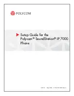
External Dimensions
Gateway Unit
(Attachment Screws and Attachment DIN Rail Type)
Hub Unit
Fixed Screws Type
Hub Unit
Attachment DIN Rail Type
Installation Environment
This product is capable for use in the environment of pollution degree 2
*1
or equivalent.
*1 Pollution Degree 2: Environment that may cause non-conductive pollution or transient conductive pollution by frost
(IEC60664-1).
1
. Installation Environment
Do not use this product in the following environment.
Location where the surrounding air temperature exceeds the range of 0 to 40
C
Location where condensation occurs due to abrupt temperature changes
Location where relative humidity exceeds 85%RH
Location exposed to corrosive gases or combustible gases
Location exposed to significant amount of dust, salt or iron powder
Location subject to direct vibration or impact
Location exposed to direct sunlight
Location where the product may come in contact with water, oil or chemical droplets
Environment that blocks the air vent [Refer to Noise Elimination and Mounting Method]
When using the product in any of the locations specified below, provide a sufficient shield.
Location subject to electrostatic noise
Location where high electrical or magnetic field is present
Location with the mains or power lines passing nearby
2
. Storage and Preservation Environment
Storage and preservation environment follows the installation environment. Especially in a long-term storage,
consider to avoid condensation of surrounding air.
Unless specially specified, moisture absorbency protection is not included in the package when the machine is
delivered. In the case that the machine is to be stored in an environment where dew condensation is anticipated, take
the condensation preventive measures from outside of the entire package, or directly after opening the package.
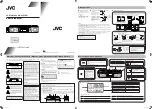
Installation and Noise Elimination
1. Noise Elimination Grounding (Frame Ground)
2. Precautions regarding wiring method
1) Wire is to be twisted for the 24V DC power supply.
2) Separate the signal and encoder lines from the power supply and power
lines.
3. Noise Sources and Elimination
Carry out noise elimination measures for electrical devices on the same
power path and in the same equipment.
The following are examples of measures to eliminate noise sources.
1) AC solenoid valves, magnet switches and relays
[Measure] Install a Surge absorber parallel with the coil.
2) DC solenoid valves, magnet switches and relays
[Measure] Mount the windings and diodes in parallel. Select a diode
built-in type for the DC relay.
4. Cooling Factors and Installation
Design and Build the system considering the size of the controller box, location of the controller and cooling factors to keep
the surrounding temperature around the controller below 40
C.
Pay a special attention to the battery unit since the performance of it would drop both in the low and high temperatures.
Keep it in an environment in the room temperature as much as possible. (Approximately 20
C is the recommended
temperature.)
35.
4 (
W
id
th
o
f
35
m
m
DIN
ra
il)
66.
5 f
ro
m
D
IN
r
ail
cent
er
35.
4 (
W
id
th
o
f
35
m
m
DIN
ra
il)
55
fr
om
D
IN
r
ail
cen
ter
Surge absorber
Relay
coil
Relay coil
R
C
+24V
0V
+24V
0V
+
-
Do not share the ground wire with or connect
to other equipment. Ground wach unit.
Earth Terminal
Grounding resistance at 100
or less
(
Class D grounding
)
Copper wire: Connect a ground
wire with a diameter of 1.6 mm
(2mm
2
: AWG 14) or larger.
Connect the ground line to the FG
terminal block on the controller
unit.
Put a tool such as a screwdriver
into the square slot and connect
the line.
Gateway
Unit