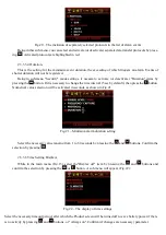
Fig. 11 – The
screen in the "Oscilloscope" mode
The main purpose of the oscillogram is to inform the user about the form of the radio signal and the nature
of its change over time in order to identify the type of transmitter.
2.3.2.3.2 Measurement channel selection.
Measurement channel selection (ANT1, ANT2) is performed in the same way as in "Search" mode: by
successively pressing the button
. The color of the oscillogram corresponds with the color of the icon of
the selected channel in the upper line of the screen. When both measurement channels (ANT1 + ANT2) work
together, two waveforms are displayed simultaneously.
2.3.2.3.3
Scanning adjustment
.
The product provides one with the ability to change the horizontal and vertical scanning buttons
and
. The horizontal scan values are 200 µs, 500 µs, 1 ms, 5 ms and 10 ms (per grid division). After switching
the current value of the horizontal scan is displayed in the lower left corner of the screen for a short time.
2.3.2.3.4 Oscillogram "freezing" and "unfreezing".
You can stop the signal rendering on a screen for a detailed signal form analysis by pressing the
button.
You then "freeze" the current oscillogram on the screen. The renewal of the display ("unfreezing") is repeated
by pressing the same button.
2.3.2.3.5 Oscillograms of some signals.
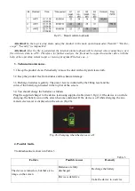
Typical oscillograms of signals of some common types of radio transmitting devices are shown in Fig.12
a) Analog transmitter
b) GSM
c) Wi-Fi
Fig.12 –
Typical oscillograms
2.3.2.
4
"Security" mode.
The device is switched to the "Security" mode when there are no unknown emissions in the room
and the implicit control of the situation is needed, such as during negotiations.
In addition, this mode can be
used for a room monitoring in the user’s absence to register new radio transmission sources, such as re-
motely controlled devices, transmitters with the function of delayed transmission, etc. You can view the
alarm logbook when the product is connected to a PC in accordance with cl.2.3.4.


