On
On
On
System OK, network overload
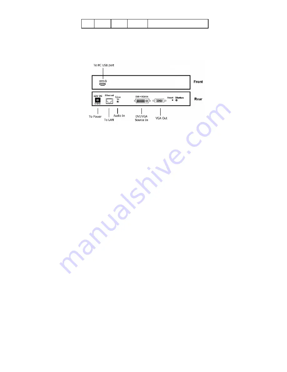
9. The [Reset] button on the CCE900-IP-T Rear panel can be
used for entering “Advance Setup Mode”, please refer to
Chapter 4. The CCE900-IP-T panel diagram is shown as
below:
2.2 Install CCE900-IP-R Receiver
1. The DVI output of the CCE900-IP-R is
[DVI-I]
(VGA + DVI-D). You
can use the accessory of VGA-to-DVI cable to connect CCE900-
IP-R to the VGA monitor. Or you can prepare a DVI-to-DVI cable
to connect CCE900-IP-R to the DVI monitor.
2. Use accessory of audio cable to connect CCE900-IP-R
[Line Out]
to speaker and plug microphone into the
[Mic In] port.
3. If you need remote keyboard/mouse function, plug keyboard
and mouse to the
[PS2]
or optional
[USB]
port.
4. If you need remote RS232 function, plug RS232 cable to the
[RS232]
port.
5. If you need remote IR function, connects optional IR receiver
cable to the
[IR extender]
port and positioned the receiver to
be visible from the front of the Display.
6. Use CAT5e/6/7 cable to connect CCE900-IP-R
[Ethernet]
to the
Ethernet switch (or directly to the CCE900-IP-T). All of CCE900-
IP-T and
4


