13
Communications wiring may be 2-wire or 4-wire but must use shielded cable with low capacitance. Wire lengths up to
2000 meters can generally be used without the need for termination resistors. Figures 4, 5a and 5b show typical RS-
485 arrangements with a RS-485/RS-232 converter and a host PC connected to a LAN.
Pulsing Fault Location
For fault location the DSP system is equipped with pulse modulation for the ground current to locate the fault more
readily. Pulse current is provided at the DSP-DPS (+) and (-) terminals, which may be directly connected to the pulse
Relay in the DSP-OHMNI-PM. It is important to observe the polarity of the connection. This 12V wiring need not be
shielded but should be 14 or 16 AWG switchboard wire for durability.
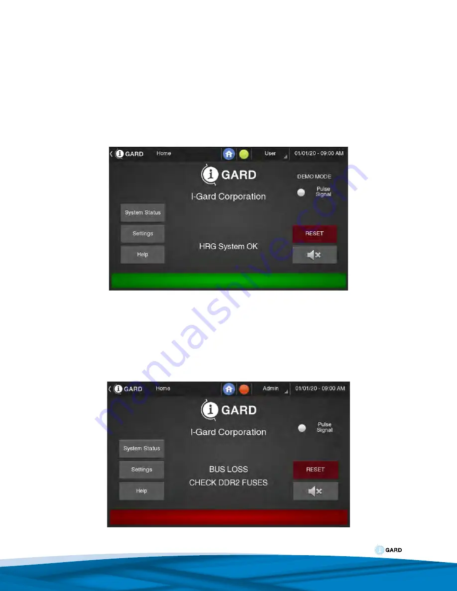
Figure 6: Home Screen
This is the home screen, which is the NORMAL starting screen after RESET is pressed. Various messages may
modify this screen following an event such a phase fault, loss of fuse, or during pulsing to provide some diagnostic
information. If the following screen appears and the local alarm sounds, then the DDR2 resistor is likely not energized
or connected.
Figure 7: Alarm Screen
Summary of Contents for DSP-OHMNI
Page 1: ...C EG30EM Instruction Manual V2 June 2020 DSP OHMNI ...
Page 11: ...9 Figure 1b DSP DCM Wiring Figure 1c System Module DSP DSM Wiring ...
Page 12: ...10 Figure 1d Power Supply DSP DPS Wiring Figure 2 Preferred Feeder Module DSP DFM Wiring ...
Page 45: ...43 Figure 41 DSP DPS System Module Connection ...
Page 46: ...44 Figure 43 DSP DLM Logging Module Connections Figure 44 DSP TDM Display Module Connections ...
Page 47: ...45 Figure 45 Typical DSP DRM Installation Connections ...
Page 50: ...www i gard com Phone 905 673 1553 Toll Free 1 888 737 4787 Fax 905 673 8472 sales i gard com ...


