


Changzhou ITC Power Equipment Manufacturing Co.,Ltd.
Changzhou ITC Power Equipment Manufacturing Co.,Ltd.
Changzhou ITC Power Equipment Manufacturing Co.,Ltd.
Changzhou ITC Power Equipment Manufacturing Co.,Ltd.
Changzhou ITC Power Equipment Manufacturing Co.,Ltd.
POWER PRODUCTS
46
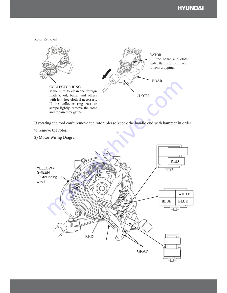
GREEN
GREEN
BLACK
BLACK
YELLOW


