


4-2
O
PERATION
Operator Manual
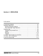
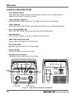
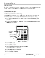
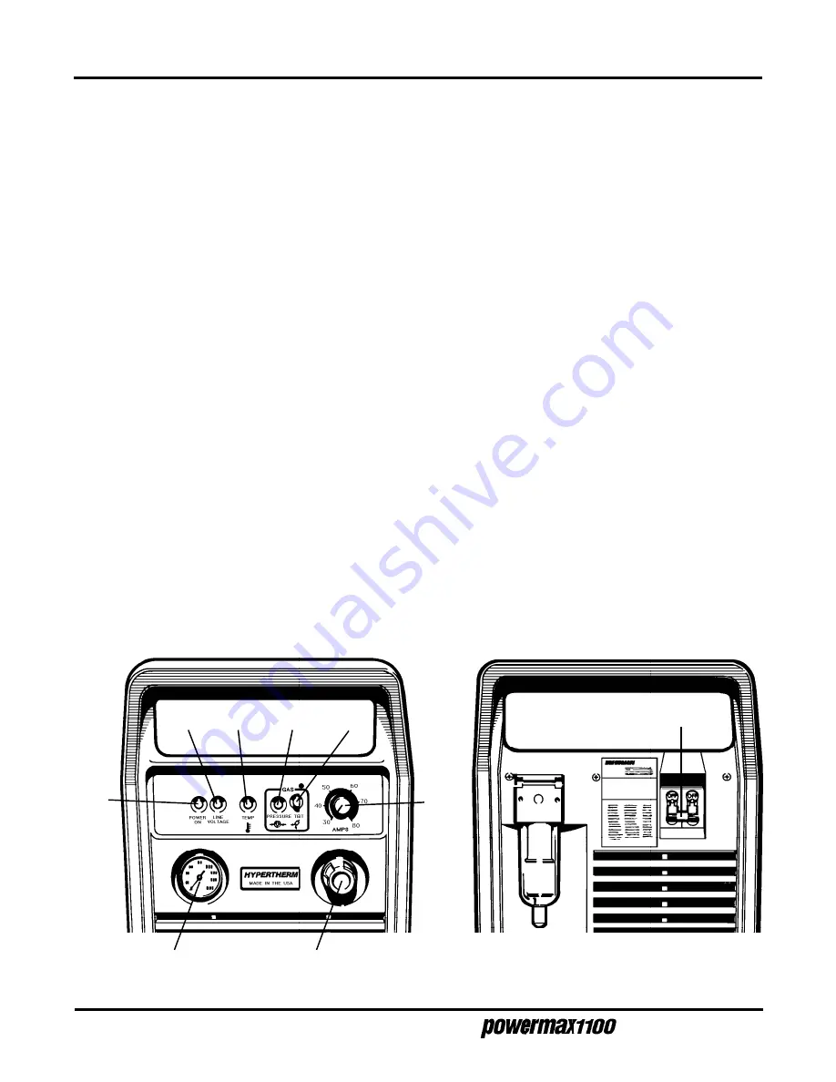
CONTROLS AND INDICATORS
•
Green POWER ON LED
When illuminated, indicates that all control circuits are activated, the torch safety interlock is
satisfied and the system is ready for operation.
•
Yellow LINE VOLTAGE LED
When illuminated, indicates that the AC line voltage is below proper operating limits.
•
Yellow TEMP LED
When illuminated, indicates that the power supply temperature has exceeded operating limits.
•
Green GAS PRESSURE LED
When illuminated, indicates that the gas pressure is within operating limits.
•
GAS TEST Switch
When pushed in, allows the operator to adjust the pressure setting.
•
AMPS Output Adjustment Knob
Adjusts output current between 30 and 80 amps.
•
Pressure Regulator
Regulates input gas pressure to the power supply.
•
Pressure Gauge
Indicates gas pressure at the power supply.
•
ON (I)/OFF (0) Power Switch
Activates the power supply and its control circuits.
GAS
PRESSURE
AMPS
ON (I)/OFF (0) Power Switch
POWER
ON
LINE
VOLTAGE
TEMP
GAS
TEST
Figure 4-1 Powermax1100 Controls and Indicators
Pressure Gauge
Pressure Regulator
4-2
Operator Manual


