HygroMatik WL-ROL 160-1200 Series Manual Download Page 38


                                                                                                                                                Page 38

11. Control

The whole operation of the reverse osmosis
unit WL-ROL is controlled by a microproces-
sor.

The control-system enables the production
process and the control of the RO-unit. The
measured values are shown on a LC-display.
The control has the protection class IP65.

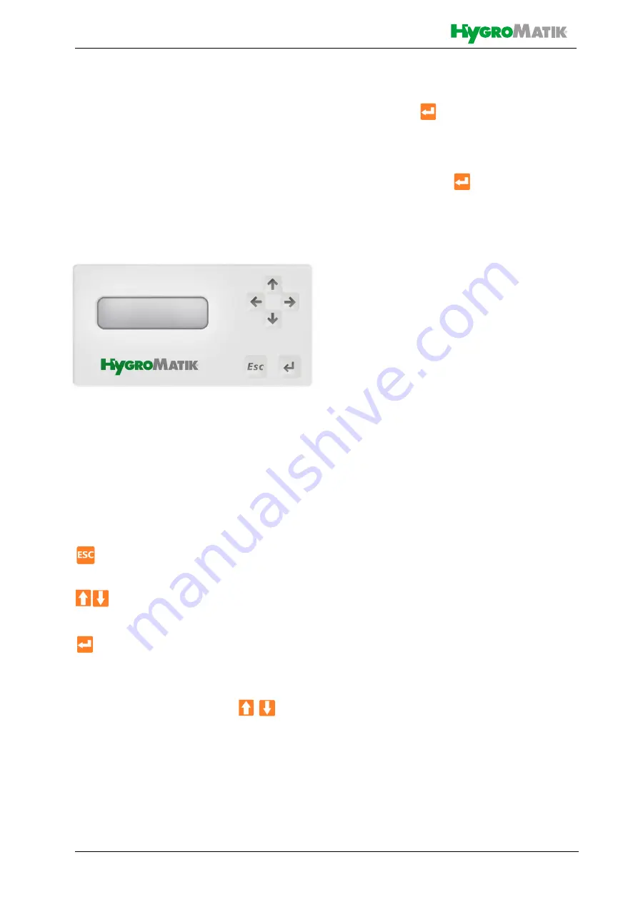
11.1 The control panel

The control panel is separated into three
zones:

the 2 operating keys ESC, ENTER     

the 4 arrow keys

LC-display

The 

operating keys

 are used to navigate

through the menus and submenus. The func-
tion of the keys is:

„ESC“: Cancel or return to the previous

level

 Arrow keys: Move within a menu, a

submenu or a selection list

„ENTER“: Acceptance and storage of a

selected setting

By pressing the arrow keys  


you can call up the read values:

Permeate conductivity

Operating hours

Remaining time (hours) until the next 
service

Access to the main menu:

»

press 

 or about 2 sec, the dis-

play shows “PASSWORD 0000“


»

enter the password using the arrow 
keys (0077)

»

confirm with 

The control system regulates the automatic
sequence for start-up, production, process
shut-down, as well as for periodic rinses by
controlling the following actuators:

Feed water valve (V

FEED

)

Permeate flush valve (V

PER

)

High pressure pump (P

HP

)

Dosing pump Antiscalant (P

ASC

)

Fault signal/alarm (potential-free 
changeover relay)

The controller is equipped with the following
digital inputs for monitoring the process:

Overpressure switch (PS

HIGH

)

Low pressure switch (PS

LOW

)

Level of permeate vessel low (PS

Min

)

Filling level permeate vessel full ( PS

MAX

)

External stand-by signal (IN

SB)

Error dosing pump antiscalant (IN

PASC

)

Malfunction feed water pre-filter (IN

FIL

)

Furthermore, the controller has a conductivity
measurement (not temperature compen-
sated) for monitoring the permeate quality,
with a freely adjustable limit value. 

This means that the unit is switched off and a
fault message is output if the limit value of the
permeate conductivity is exceeded during
operation.

Summary of Contents for WL-ROL 160-1200 Series

Page 1: ...FlexLine Reverse osmosis plants MANUAL WLROL EN E 8881184 WLROL ENj WL ROL 160 1200...

Page 2: ...S EN All Rights reserved Current version of this manual to be found on www hygromatik com HygroMatik GmbH grants the legal user of this product or device the right to use the Work s solely within the...

Page 3: ...rs 11 4 3 Operating conditions of the unit 12 4 3 1 Recovery value 12 4 4 Operating sequence 13 4 5 Mechanical construction 14 4 6 Flowshart 16 5 Mechanical installation 18 5 1 Environment Parameters...

Page 4: ...scalant canister 34 9 3 3 Replacing the UV lamp 34 9 3 4 Reset maintenance counter 34 9 4 Special maintenance and repairs 35 9 4 1 Membrane exchange 35 9 4 2 Replacing the metering pump fuse 35 9 5 Ma...

Page 5: ...g and service hour counter 56 11 6 14 Function test relay outputs 57 11 6 15 Function test alarm output relay 57 11 6 16 Select language 58 11 6 17 Change password 58 11 6 18 Reset password 58 11 6 19...

Page 6: ...Terms used with graphics or drawings 1 2 Documentation Retention Please retain these operating instructions in a secure always accessible location If the product is resold turn the documentation over...

Page 7: ...ems The limit and guide values of the Ger man Drinking Water Ordinance must be taken into account Frost protection and protection against excessive moisture must be ensured The permitted surrounding t...

Page 8: ...g and maintenance of the unit must not be undertaken by children with out supervision The installation room must be adequately ventilated and be equipped with a floor drain A water stop mechanism e g...

Page 9: ...ling of additional components is permitted only with the written consent of the manufacturer 2 1 5 Electrical Risk of electrical shock Hazardous electrical voltage Any work on the electrical system to...

Page 10: ...e from shipment and or missing parts immediately notify the carrier or supplier in writing Time limits for filing freight claims with ship ping companies are Time limits for some services subject to c...

Page 11: ...strial applications 4 2 Influencing factors The performance of the reverse osmosis membrane depends strongly on the following parameters Water inlet pressure at the membrane By lowering the working pr...

Page 12: ...timise permeate output by adju sting the flow rates Ref 1 The basis for this is the relevant recovery value of the system see technical data For example the recovery value for the ROL320 is 68 at a ra...

Page 13: ...water line scope of delivery to the expansion ves sel or directly to the consumer The quality of the permeate leaving the system is controlled by the conductivity sensor EC PROBOUT The production pro...

Page 14: ...nes 4 Antiscalant tank 5 Pump 6 Check valve for antiscalant injection 7 System feedwater solenoid valve 8 Drain water outlet 9 Permeat outlet 10 Antiscalant pump WL ROL 160 460 Ref 2 J Prefilter CPC 2...

Page 15: ...2 UV lamp 3 Pressure container membranes 4 Antiscalant tank 5 Pump 6 Check valve for antiscalant injection 7 System feedwater solenoid valve 8 Drain water outlet 9 Permeat outlet 10 Antiscalant pump...

Page 16: ...brane F Prefilter CV Non return valve PS Pressure switch BV Manual ball valve C P Control FR Flow limiter SV Solenoid valve PI Pressure gauge EV Expansion vessel RV Manual control valve EC Conductivit...

Page 17: ...10 CPP RO Membrane F Prefilter CV Non return valve PS Pressure switch BV Manual ball valve C P Control FR Flow limiter SV Solenoid valve PI Pressure gauge EV Expansion vessel RV Manual control valve...

Page 18: ...aged Ambient temperature must lie between 5 and 40 C 41 and 104 F in order to protect the unit electronics against damage frost may damage the steam cylinder the solenoid valve and pump as well as mak...

Page 19: ...ver operate the unit with the permeate line closed 5 2 3 Connection of the expansion vessel Mount the holder of the expansion tank on a stable wall or ensure a secure stand on the floor If necessary c...

Page 20: ...ible rest pressure Switch off the system press ESC for 2 seconds then disconnect the system from the power supply remove the plug Remove the filter housing using the installation key supplied For main...

Page 21: ...con tainer as shown pay attention to the position direction of the seal Make sure that the lip seal is not dam aged Reassemble the top caps of the con tainers in the correct position and secure them w...

Page 22: ...to fit and or remove the lamp and the quartz Open the rubber cap A and unscrew the plug B Slide the lamp D approximately fi ve centimetres out of the chamber G Securely holding the end of the lamp D...

Page 23: ...le range of water pressure 1 5 to 4 bar 22 to 58 psi 150 000 to 400 000 Pa If the pressure is below 1 5 bar install a pressure booster if it is above 4 bar install a pressure reducer after the reverse...

Page 24: ...llation checklist ALL screw connections and hoses firmly connected Water supply line flushed before making connections Water connection properly installed Water discharge properly installed Does blow...

Page 25: ...trostatical discharge 7 1 Procedure for electrical installation Insert the plug into a suitable socket The performance values are given in the technical data 7 2 Remote ON OFF and alarm relay connect...

Page 26: ...L ROL 1 L 2 earth 3 N 230 V 50 60 Hz Input for system power supply x 4 L 5 earth 6 N 230 V Output for pump supply x 7 L 8 earth 9 N 230 V Output for dosing pump x 10 L 11 earth 12 N 230 V Output for i...

Page 27: ...unit produces a higher permeate quantity in the first 2 4 hours which is combined with a higher conductivity The pump may only be operated with the water inlet valve open otherwise it could be damage...

Page 28: ...Press ENTER for two seconds the display shows PASSWORD 0000 Enter service password Confirm with Enter Select menu item 14 system test Press Open the water inlet valve SV01 Press Open the flush valve...

Page 29: ...permeat conductivity probe E attachment for sampling permeat Using the example of WL ROL 1000 Circulating flow rate 450 l h Concentrate flow rate 470 l h This results in a recovery value of 68 percent...

Page 30: ...ragm s To increase the pump pressure proceed as follows Rotary vane pump in models from 100 l h to 320 l h Open or close the by pass valve bypass with a slotted screwdriver see figure previous page Mu...

Page 31: ...alant canister take the required amount of antiscalant depending on the water hardness from the table in the chapter Technical Data Using a measuring cup thin the anti scale in the canister with perme...

Page 32: ...ers are within the limits given in chapter 4 3 To ensure the functionality of the seals the system must be put into operation within one year of the delivery date 8 7 Break of use The functionality of...

Page 33: ...h is insufficient for the application downstream of the reverse osmosis system Too much increase in the conductivity of the water produced to a value too high for the application downstream of the sys...

Page 34: ...closed and there is no pressure on the water line Remove the pre filter with suitable tools Remove the old filter cartridge and clean the inlet Replace the O ring if necessary Moisten the new O ring a...

Page 35: ...the conductivity of the water produced to a level that is excessive for the application connected downstream of the reverse osmosis system Before replacing the membrane s check the following The ROL u...

Page 36: ...the actual value within the first minutes 9 5 3 Maintenance every two months Check that there is not too much free chlorine at the outlet less than 0 25ppm Replace the pre filter cartridge Every 2 mon...

Page 37: ...edures in reverse order Dismantling of the unit may only be per formed by qualified personnel Electrical dis mantling may only be performed by trained electricians Obey the safety guidelines in sectio...

Page 38: ...sec the dis play shows PASSWORD 0000 enter the password using the arrow keys 0077 confirm with The control system regulates the automatic sequence for start up production process shut down as well as...

Page 39: ...avoid damage a delay of 3 seconds is given after the input solenoid valve has opened When the MaxPressure condition is reached the control unit goes into stand by mode the input solenoid valve closes...

Page 40: ...meate tank is full The unit performs a module rinse if programmed and then goes into stand by mode Shows the permeate conductivity Shows the remaining time in hours until the next service Shows the sy...

Page 41: ...ly and eliminate the cause of the alarm Further information can be found in the chap ter Troubleshooting The overpressure switch PSHIGH for the max permitted operating pressure has switched The system...

Page 42: ...ng to the next digit within the input field Button ESC In menu level To leave the menu level and return to the operating display level In the parameter To return to the previous iA longer press 2 sec...

Page 43: ...arrow keys you spec ify the time period between the periodic mod ule flushes e g change 24h to 48h usage pause Confirm the selection with The program jumps back to the main menu In the factory setting...

Page 44: ...85 0 35 6685 0 35 6685 3XPS 7 03 1 52 6 23 0 7 287 1 1387 0 6 50 6 1 6 5 1 w6 52 2 0 7 287 w6 2 9 217 7 1 0 5 75 52 6 23 5 1 w6 8 5 w6 6 7 32 17 1 6 1 6 1 1 6 6 2 9 1 2 9 6 1387 6 2 9 217 7 1 2 9 1 21...

Page 45: ...1 352 1 1 352 6 7 0 PLQ VHF 6 PLQ VHF K 5 6 5 2817 17 5 12 50 5 6 7 50 1 50 6 287387 50 1 2 217 7 287387 50 1 217 7 5 6 7 6 67 07 67 5 6 5 2817 17 5 6 5 6 6 59 17 5 6 5 6 6 59 17 5 12 6 67 0 7 67 50 7...

Page 46: ...ctivity of the feed water ROH MIX the other sensor that of the permeate Both con ductivity sensors are pre calibrated ex works In the case of recalibration during maintenance the calibration can be ca...

Page 47: ...g 11 6 2 Calibration of the probe zero point Remove the conductivity probe from the flow assembly and dry it Select 2A CAL ZERO in the main menu A conductivity value is now displayed in the upper line...

Page 48: ...djustable limit value for the permeate conductivity the unit can be stopped and an alarm message issued if the permeate quality is reduced Select 3 LIMIT OUT in the main menu Press the arrow keys to s...

Page 49: ...nu If a module flush is followed by a longer standstill period an increased conductivity value may temporarily occur If the parameter 3C is set to ON this will lead to an unin tended shutdown of the s...

Page 50: ...level switch the minimum fill level in the permeate vessel can be moni tored and the system can be started automat ically if the pressure falls below the required level Select 5 LOW LEVEL Press the a...

Page 51: ...e ENABLED active ex works DISABLED inactive Confirm the selection with If the set point function has been activated the program jumps to submenu 6B Press the arrow keys to set the switching direction...

Page 52: ...ot change this Otherwise there is a risk of dam age to the system Press the arrow keys to set the time of delay 0 Sec no delay see note at the end of the chapter Confirm the selection with The program...

Page 53: ...means of a pressure switch between the high pressure pump and the RO modules If a maxi mum pressure set on the pressure switch is reached during production e g due to an overly restricted concentrate...

Page 54: ...umn softening system to the control so that the RO unit goes into standby mode for the duration of the regeneration Press the arrow keys to select if relay input should be active or inactive Confirm t...

Page 55: ...roduction is started up YES active NO inactive Confirm the selection with The program jumps to submenu 11D By pressing the arrow keys you set whether a flush should be carried out before each start Co...

Page 56: ...main menu 11 6 13 Operating and service hour counter The operating hours counter always runs when the system is in production mode It is for general information and has no further control function It...

Page 57: ...ESC to return to the main menu To avoid damage to the unit Always acti vate the feed water valve first before acti vating the pump 11 6 15 Function test alarm output relay In this submenu you can manu...

Page 58: ...he program jumps to the screen Press the arrow keys to enter your new password again Confirm the selection with The program jumps to the screen If the entry is incorrect CONFIRM ERROR appears on the d...

Page 59: ...l free fault signal output of the dosing pump or the level switch empty indicator in the dos ing vessel can be connected to the controller If the INPASC input is switched the control system can switch...

Page 60: ...he selection with The program jumps to submenu 20C Press the arrow keys to set the time of delay 0 Sec no delay see note at the end of the chapter Confirm the selection with The program jumps back to...

Page 61: ...03 07 10 13 16 08 11 14 17 09 12 15 18 41 42 43 37 38 39 40 35 36 33 34 24 25 26 27 28 29 30 31 32 22 23 blue black red Main power 230 VAC Highpressurepump P HP 1 phase max 2A Dosingpump Antiscalant...

Page 62: ...Page 62...

Page 63: ...Replace the pressure switch Water pressure too high Re adjust the pump pressure Membrane s is are blocked Replace membrane The PSLOW pressure switch is not calibrated or is not working correctly Check...

Page 64: ...replace it if it is damaged Control board or the solenoid valve coil is not supplied with voltage Restore the power supply to the control board and or check the connections and the solenoid valve sup...

Page 65: ...Page 65 13 Declaration of Conformity...

Page 66: ...Page 66...

Page 67: ...ronic ballast 230V 50 60HZ for lamp 10 21 W x ROKC00BLD1 Acc Blending kit for WL ROC 25 80l h with adjustable mixing ratio and conductivity sensor x ROKC00BLD2 Acc Blending kit for WL ROC 140l h with...

Page 68: ...WREN Spare Spanner for 10 filter DP model x x ROKC00FLT2 Spare Carbon block cartridge filter CB EC 10 SX 10 m x x ROKC00FLT3 Spare Sediment melt blown filter CPP 10 SX 5 m x x ROKC00OR10 Spare 10 wate...

Page 69: ...L00IV14 Spare SOLENOID VALVE SV2 1 4 G F 230Vac ELETTROVALVOLA BOBINA x ROKC00P064 Spare PE PIPE 6 4 x ROKL00FL20 Spare Flow meter D 20 320 lph x ROKL00FL25 Spare Flow meter D 25 1000 lph x ROKL00FL32...

Page 70: ...vessel consumer meters Connection to the drinking water system yes no Softening system connected yes no Hoses to the an scalant pump and canister connected if available yes no Prefilter and membranes...

Page 71: ...ess feed water dH Conductivity feed water s cm Temperature feed water C Conductivity permeate s cm s cm Operation pressure bar switch on pressure max 2 bar bar switch off pressure max 4 bar bar Sample...

Page 72: ...Page 72 This page intentionally left blank...

Page 73: ...SPA Page 73 This page intentionally left blank...

Page 74: ...feed water Total Dissolved Salt ppm feed water conductivity S cm 2 4 2 2 4 4 size of low energy membranes 4 x 40 4 x 40 XL 4 x 40 4 x 40 XL 7 9 8 8 7 4 7 9 8 1 8 8 permeate pressure bar electrical pow...

Page 75: ...t WL ROL 160 WL ROL 320 WL ROL 460 WL ROL 600 WL ROL 1000 WL ROL 1200 Canister size l Dosing antiscalant l 0 80 0 90 2 20 2 90 2 60 3 10 Dilution factor 25 00 22 22 9 09 6 90 7 69 6 45 Dosing antiscal...

Page 76: ...Ein Unternehmen der Gruppe 100 Lise Meitner Str 3 D 24558 Henstedt Ulzburg Phone 49 0 4193 895 0 Fax 33 eMail hy hygromatik de www hygromatik com member of CAREL Group...

Reviews: