Page 35
supplied by the customer) need only be low-
voltage proof. If the system is modified on the
customer site, the digital inputs on the main
board and possibly on the extension board
must be parametrized accordingly (s. section
x).
The parameters in question are indicated
in context of the respective terminal wiring
depicted hereunder.
10.5.3.1 Terminal wiring for supply
air humidification (standard
delivery)
1-step operation
Operation with active humidity sensor or
external controller
When driving the high-pressure nozzle sys-
tem with an active humidity sensor or through
an external controller ( e.g. a PLC), physical
control signals in the range of 0...10 V, 0...20
mA or 0...140
Ω
can be used. For each of
the signal variants a particulat terminal is pro-
vided on the mainboard. In all cases, refer-
ence potential is terminal 4, „GND“.
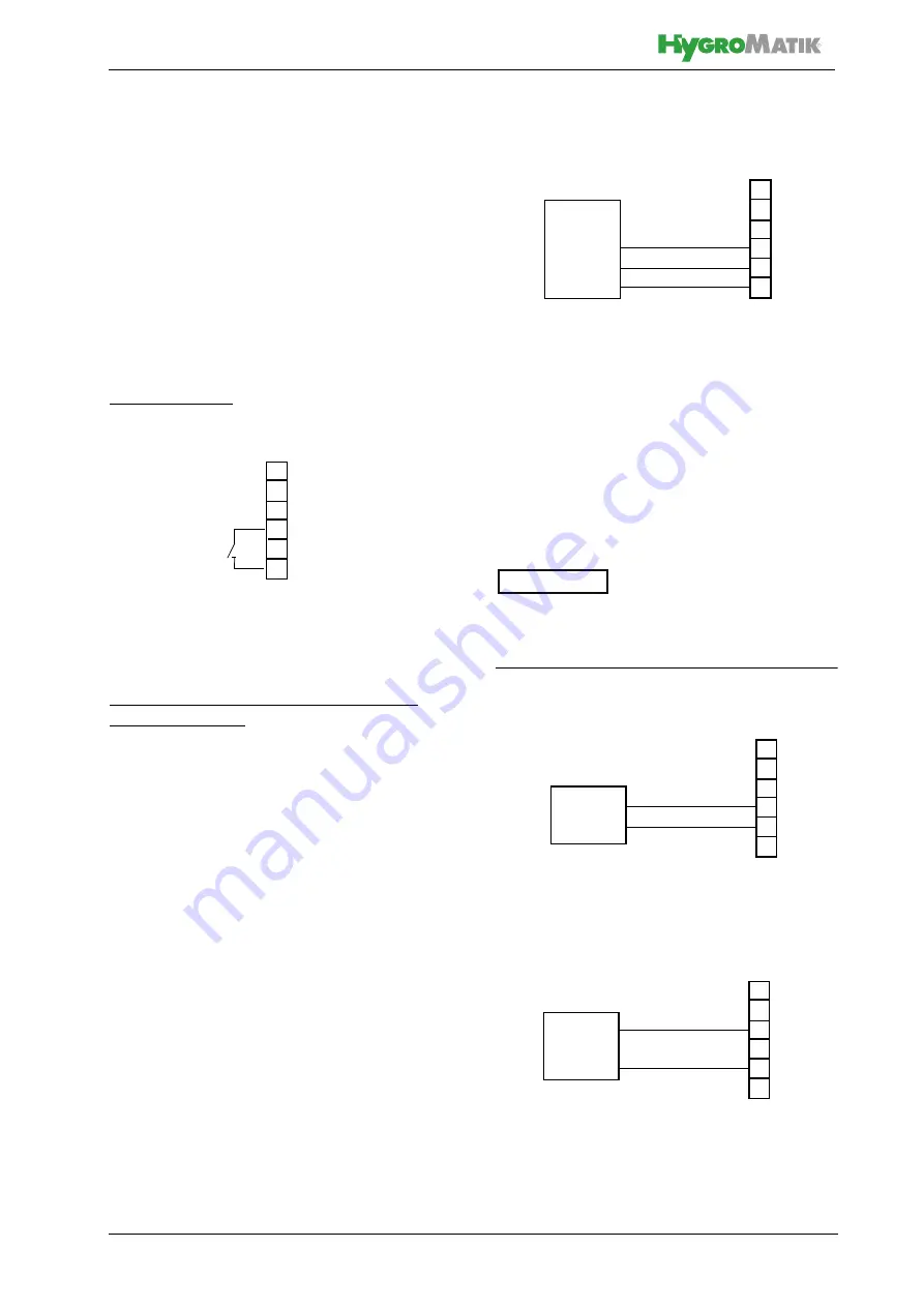
Wiring variants (exemplary):
If an external control signal 0...10 V is used,
wiring is to be made to terminal 4 (GND) and
5 (signal) . Wiring for a resitive signal 0...140
Ω
is across terminals 4 and 7. A humidity
sensor with current output 0...20 mA is to be
wired across terminals 4 (GND) and 6.
Active humidity sensors require an external
supply voltage. Terminal 3 pr20 VDC
for that purpose.
20 VDC
Terminal strip on ST08
Terminal 3/5 wiring on the mainboard (terminal
strip on ST08) for 1-step operation
3
45
6
7
8
S1
S1: NO contacts
3
45
6
7
GND
0...10V
Terminal strip on ST08
8
External controller
Terminal 4/5 wiring on the mainboard (terminal
strip on ST08) for connection of a 0...10 V external
control signal
3
45
6
7
+20 VDC
Humidity sensor
GND
0...10V
8
Terminal 3/4/5 wiring on the mainboard (terminal
strip on ST08) for connection of a humidity sensor
0...10 V
Terminal strip on ST08
3OHDVHQRWH
3
45
6
7
GND
8
Terminal 4/6 wiring on the mainboard (terminal
strip on ST08) for connection of a 0...20 mA control
signal
0...20mA
Terminal strip on ST08
External controller


