background image

22 

5.6


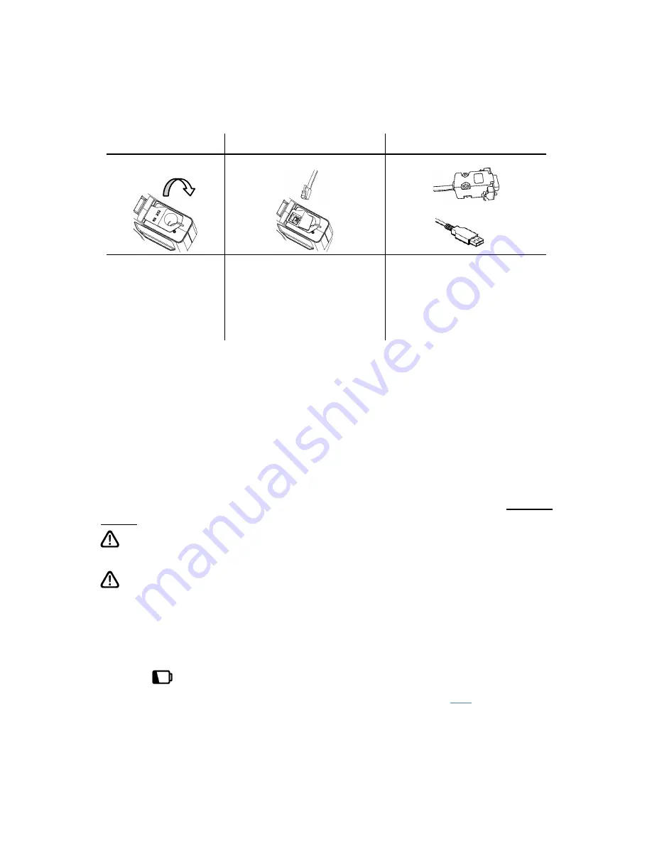
Connecting the Luminometer to the PC 

Now  connect  the  serial  interface  cable  (as  supplied  with  the 

luminometer)  between  the  luminometer  and  one  of  the  RS232  or 

USB ports on your PC: 

Step 1 

Step 2 

Step 3 


OR 


Fold back rubber 

cover to access 

RS232 socket 

Insert small RJ10 plug 

into luminometer’s 

RS232 socket 

Connect other end to 

the PC’s COM port or 

USB port depending on 

the Cable included with 

your luminometer. 

NOTE

: Select the appropriate RS232 or USB cable most suitable for 

your PC. A USB-to-RS232 adapter can also be used. Please contact 

your local distributor for further details. 

6.


Operator Maintenance 

The  luminometer  does  not  require  any  specific  routine  operator  or 

service engineer maintenance. 

6.1


Cleaning the Luminometer Case 

Clean  the  luminometer  case  when  required  using  a  dry  or  slightly 

damp cloth only. 


WARNING

:  Never  clean  the  luminometer  using  a  wet  cloth  or 

washing it with water. 


CAUTION: 

Do  not  use  solvents  or  other  strong  cleaning 

solutions as these may attack and deform the luminometer’s plastic 

components, and seriously degrade its performance. 

6.2


Replacing the Batteries 

For  best  results,  the  batteries  should  be  replaced  when  the  low 

battery 

 warning icon is flashing. 

For details on how to fit new batteries (see section 

2.2

). Take care 

not to mix the old batteries with the new ones. 

IMPORTANT

:  Always  dispose  of  old  batteries  in  accordance  with 

your local authority regulations. 

Summary of Contents for EnSURE v2

Page 1: ...I Ultrasnap SureTrend and dataSURE II are trademarks of Hygiena LLC Operating Precautions and Limitations of Use The following symbol is used in this manual Description CAUTION WARNING IMPORTANT Hygie...

Page 2: ...P PROGRAM TEST POINTS AND PASS FAIL LIMITS _____________________ 10 3 3 TEST PLANS ______________________________________________________ 11 3 4 ESTABLISHING ATP PASS FAIL LIMITS _____________________...

Page 3: ...__ 23 7 TROUBLESHOOTING ________________________________________________ 24 7 1 LUMINOMETER BEEPS _______________________________________________ 24 7 2 TROUBLESHOOTING TIPS __________________________...

Page 4: ...evels of contamination on surfaces water and product samples 1 Remove swab from test tube and collect sample Refer to instructions included with testing device 2 Place swab back in test tube 3 Break S...

Page 5: ...ased from inside these cells along with any free ATP picked up from the surface by the swab is now available to react with the chemistry in the bulb of the device When the Luciferin Luciferase enzymes...

Page 6: ...ng Practices GMP or sanitation plan 1 4 Test Devices and Accessories Device Cat No Description UltraSnap US2020 Surface total ATP test device SuperSnap SUS3000 High sensitivity total ATP test suited f...

Page 7: ...lect and Exit button Up increase button Start accept button Down decrease button Program select button Statistics shortcut button The functions of the keypad are explained in detail in the following s...

Page 8: ...Cell Voltage Relative Capacity Alkaline 1 5V 1 0 NiMH 1 2V 0 6 NiCD 1 2V 0 5 The unit requires two batteries of size AA LR6 or E91 TIP For best results always use a quality brand of Alkaline battery...

Page 9: ...ely The unit will then perform an internal 15 second calibration see section 2 7 NOTE If the clock is not set the unit will automatically enter the time and date set up mode see section 3 8 before per...

Page 10: ...ement reading in Relative Light Units RLU Retested icon identifies the failed test result as having been retested see section 4 2 Retest result icon identifies the Program location or test result as a...

Page 11: ...and is flat TIP The button can be pressed at any time to access the set up menu options see section 3 When the calibration is complete the luminometer is ready to perform a sample measurement For deta...

Page 12: ...button Use the and buttons to scroll through the menu list and then press the button to select the required menu option or the button the exit the menu The following 11 menu options are available User...

Page 13: ...uminometer or set using the SureTrend software If a location name is entered and threshold set in SureTrend and then downloaded to the luminometer the threshold values can t be changed via the luminom...

Page 14: ...ocations specified in the order in which they would normally be tested Having selected the TEST PLAN menu option use the and buttons to scroll through the list of Test Plans and then press the button...

Page 15: ...guide included with your system or visit the resources available on www hygiena com 3 5 Viewing Stored Test Results The luminometer can store a maximum of 2000 test results in its internal memory eve...

Page 16: ...to exit the option 3 8 Setting the Clock Time and Date To set or change the clock time date and format select the CLOCK menu option by pressing the button Scroll to CLOCK and press Then use the and bu...

Page 17: ...ready to perform readings Quick Boot can be turned off and the luminometer will perform a more in depth system check the next time it is turned on The more in depth system check takes 60 seconds NOTE...

Page 18: ...able or disable the warning beeps This will toggle the bell icon from enabled to disabled Press the button to accept the settings increase or decrease duration 5 to 60 set duration enable or disable w...

Page 19: ...corded NOTE The Save Tests mode will be set back to ON when the luminometer is turned off and back on again When Save Tests mode is set to OFF RESULTS NOT SAVED will appear at the bottom of the LCD To...

Page 20: ...y shows the following details Various keypad options are now available as detailed in each of the following sections Button Action Section Access set up menu options 3 Select different User ID 3 1 Sel...

Page 21: ...e displayed WARNING Always ensure that the exterior of the testing device is clean and dry before inserting it into the luminometer Never insert anything other than a Hygiena testing device into the l...

Page 22: ...location was a failure Having selected retest mode signified by the icon next to the Prog perform the sample measurement in the usual way using a new testing device see section 4 1 Once the retest mea...

Page 23: ...on your computer has been disabled Open My Computer right click on the CD drive and select AutoPlay If this does not start the install program open the CD folder and run the Setup application NOTE Yo...

Page 24: ...ardware Wizard does not start check the following a You have sufficient permissions to run the wizard b Verify there are no existing hardware problems in device manager c Verify the Universal Plug and...

Page 25: ...intenance The luminometer does not require any specific routine operator or service engineer maintenance 6 1 Cleaning the Luminometer Case Clean the luminometer case when required using a dry or sligh...

Page 26: ...ocket using water or a very mild detergent solution ensuring that the pocket is completely dry and clean before putting it back into the luminometer WARNING Do not use solvents or other strong chemica...

Page 27: ...use the luminometer emits a variety of different beeping sounds Beep Type Possible Causes Short high pitched tone Luminometer turned on or off Sample measurement started Communications established wit...

Page 28: ...window is dirty Display window is scratched or dented Display or luminometer damaged or faulty Keypad button has no effect when pressed Some buttons only work when selecting particular luminometer fu...

Page 29: ...dirty or severely scratched Luminometer damaged or faulty E4 User settings undefined The user configurable settings are undefined check and re set the CLOCK format User Plan and Prog data E5 Program...

Page 30: ...n of any part of the luminometer or the use or attachment of any peripheral not supplied or specified by Hygiena will void this Warranty WARNING Use only the accessories and consumables supplied by Hy...

Page 31: ...t resolution 1 RLU Measurement time 15 seconds Measurement noise 5 or 5 RLUs User IDs 200 IDs of 16 characters Programmable result thresholds 5001 programs Programmable location names 5001 names of 20...

Page 32: ...alkaline batteries or rechargeable NiMH NiCD batteries of types specified in section 10 WARNING Do not use batteries with individual cell voltages greater than 1 65V as this will cause permanent damag...

Page 33: ...1 The luminometer is manufactured under ISO 9001 controls Declaration of Conformity The luminometer has been designed in accordance with and satisfies the requirements of article 11 of the Low Voltage...

Reviews: