


35
A1: Lifting Information
1.
Verify your lifting has capacity for the weight of the HarborHoist. See Table 1 for weight of lift.
2.
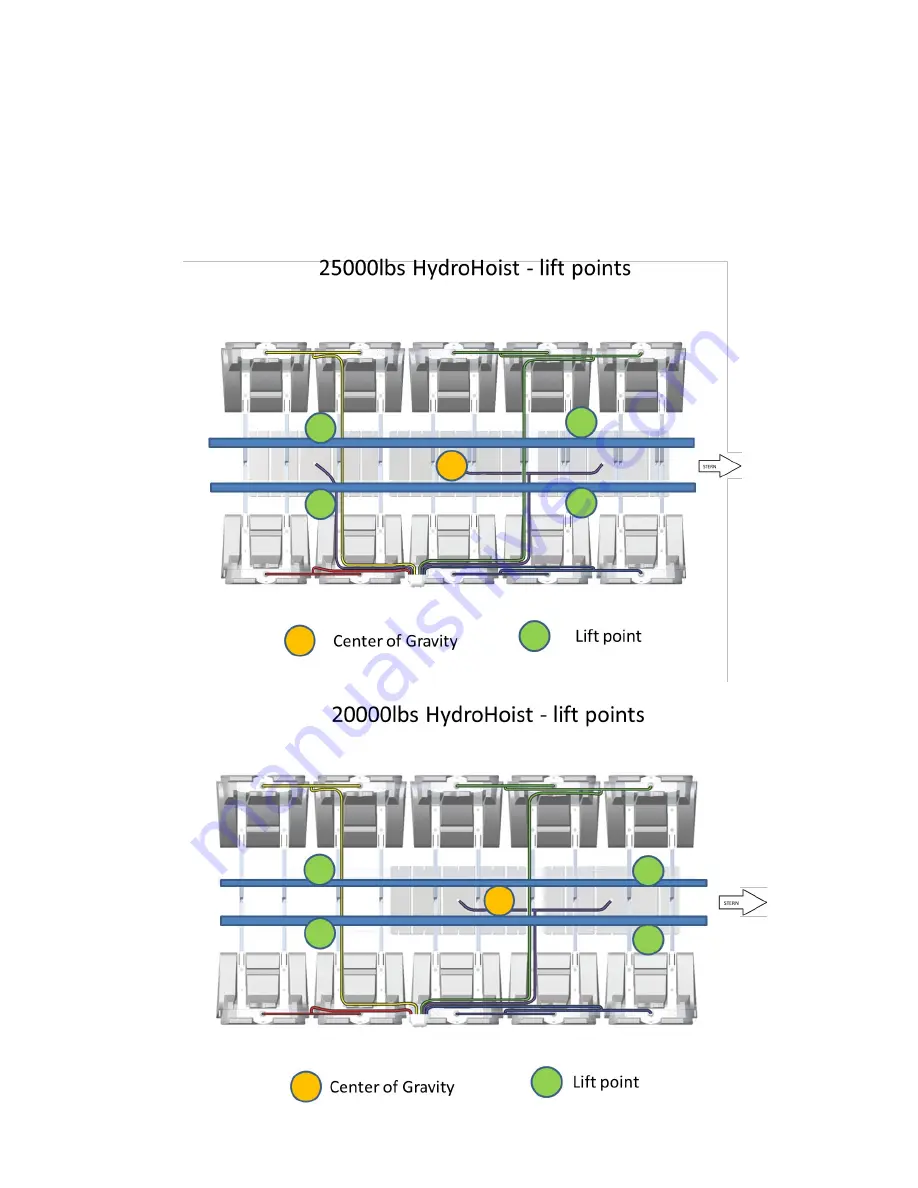
You will need four straps that can support the load fastened around the Cross Channels outside the
Hull Pads, and then attached to a crane or fork lift.
3.
Always lift around the center mass of the lift. See diagrams below for locations to attach the straps.