Pg 3.14
S23H
ANGLE BRAKE ADJUSTMENT
The clamping force on the swivel brake can be adjusted to ensure that the Head
is held securely and does not move during cutting. The brake handle should be
adjusted so that it does not "bottom out" or hit it's movement limit, yet holds the
head securely.
ANGLE BRAKE ADJUSTMENT PROCEDURE
STEP 1
Loosen locking cap screw "B" with a 1/4 allen key.
STEP 2
Tighten all 4 set screws "A" until snug with a 5/32 allen key.
STEP 3
Back out the "A" screws 1/4 of a turn.
STEP 4
Tighten the locking cap screw "B".
STEP 5
Swing the head to 45
O
and back to ensure that the head moves freely
and does not bind on the pivot surfaces. Continue to step 6 if necessary.
STEP 6
Adjust the clamping force bolt "C" with a 3/4" wrench. If tightened too
much the locking handle will "bottom out" and not hold the head firmly.
DRIVE BELT REPLACEMENT
The drive belt on the S-23 is a long life grooved belt. It should last for many of hours of operation and should
rarely require replacement. See the BLADE DRIVE ASSEMBLY drawing on Pg 6.2.
HEAD DOWN LIMIT SWITCH
The Head down limit switch operates to cut power to the blade motor and the
coolant pump motor when the Head has descended to the bottom of its travel.
The Head is adjusted so that the blade will descend slightly past the level of the
vise wear strips. This setting is critical to ensure that the blade has cut fully
through the stock. The Head Down Limit Switch is located at the back of the
head near the head cylinder.
Adjustment of the limit switch is made by changing the position of the set bolt
which is located beside the horizontal pivot pin on the pivot link. Lengthening the
set bolt will cause the limit switch to activate sooner as the spring post meets
the limit switch roller. Shortening the setting bolt by turning it into the pivot link
will lengthen the time before the Head limit switch is activated.
Head Down Limit Switch
& Adjusting Bolt.
A
B
C
Angle Brake Adjustment
Screws
Summary of Contents for S-23H
Page 1: ...I N B A N D S A W T E C H N O L O G Y OPERATIONS MAINTENANCE M A N UA L ...
Page 3: ...THIS PAGE INTENTIONALLY LEFT BLANK ...
Page 6: ...SECTION 1 INSTALLATION SECTION 1 INSTALLATION ...
Page 7: ...SECTION 1 INSTALLATION ...
Page 12: ...SECTION 2 OPERATING INSTRUCTIONS SECTION 2 OPERATING INSTRUCTIONS ...
Page 13: ...SECTION 2 OPERATING INSTRUCTIONS ...
Page 19: ...THIS PAGE INTENTIONALLY LEFT BLANK ...
Page 20: ...SECTION 3 MAINTENANCE AND TROUBLE SHOOTING SECTION 3 MAINTENANCE AND TROUBLE SHOOTING ...
Page 21: ...SECTION 3 MAINTENANCE AND TROUBLE SHOOTING ...
Page 28: ...Pg 3 17 S23H SERVICE RECORD NOTES DATE SERVICED BY COMMENTS ...
Page 29: ...THIS PAGE INTENTIONALLY LEFT BLANK ...
Page 30: ...SECTION 4 ELECTRICAL SYSTEM SECTION 4 ELECTRICAL SYSTEM ...
Page 31: ...SECTION 4 ELECTRICAL SYSTEM ...
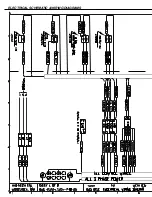
Page 35: ...ELECTRICAL SCHEMATIC WIRING DIAGRAMS ...
Page 36: ......
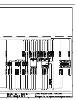
Page 37: ...ELECTRICAL SCHEMATIC WIRING DIAGRAMS ...
Page 38: ......
Page 39: ...THIS PAGE INTENTIONALLY LEFT BLANK ...
Page 40: ...SECTION 5 HYDRAULIC SYSTEM SECTION 5 HYDRAULIC SYSTEM ...
Page 41: ...SECTION 5 HYDRAULIC SYSTEM ...
Page 43: ...Pg 5 28 S22 23H CYLINDER ASSEMBLIES Piston assemblies Gland assemblies ...
Page 44: ...Pg 5 29 S22 23H HYDRAULIC SCHEMATIC and PLUMBING DIAGRAM ...
Page 45: ...Pg 5 30 S22 23H ...
Page 46: ...SECTION 6 MECHANICAL ASSEMBLIES SECTION 6 MECHANICAL ASSEMBLIES ...
Page 47: ...SECTION 6 MECHANICAL ASSEMBLIES ...
Page 48: ...Pg 6 31 S23H 2001a GUIDE ARM CARBIDE ASSEMBLIES SECTION 6 MECHANICAL ASSEMBLIES ...
Page 49: ...Pg 6 32 S23H 2001a BLADE DRIVE ASSEMBLY ...
Page 51: ...Pg 6 34 S23H 2001a HM4A GEAR BOX ASSEMBLY ...
Page 52: ...Pg 6 35 S23H 2001a IDLERWHEEL ASSEMBLY 01 2345 1 345 1 6 7809 849 59 9 3 01 1 ...
Page 53: ...Pg 6 36 S23H 2001a BLADE BRUSH ASSEMBLY ...
Page 54: ...Pg 6 37 S23H 2001a COUNTER BALANCE SPRINGASSEMBLY ...
Page 55: ...Pg 6 38 S23H 2001a PIVOT LINK ASSEMBLY ...
Page 56: ...Pg 6 39 S23H 2001a 0 1 Pivot link parts list ...
Page 57: ...Pg 6 40 S23H 2001a FRONTVISE ASSEMBLY ...
Page 58: ...Pg 6 41 S23H 2001a HYDRAULIC POWER PACK ...
Page 61: ...THIS PAGE INTENTIONALLY LEFT BLANK ...
Page 62: ...SECTION 7 OPTIONAL ASSEMBLIES SECTION 7 OPTIONAL ASSEMBLIES ...
Page 63: ...SECTION 7 OPTIONAL ASSEMBLIES ...
Page 64: ...Pg 7 45 S23H SECTION 7 OPTIONAL ASSEMBLIES WORK STOP ...
Page 67: ...Pg 7 48 S23H 30O MITRE CUTTING ...
Page 68: ...SECTION 8 SPECIFICATIONS SECTION 8 SPECIFICATIONS ...
Page 69: ...SECTION 8 SPECIFICATIONS ...
Page 71: ...Pg 8 50 S23H LAYOUT DRAWINGS ...
Page 72: ...Pg 8 51 S23H ...
Page 73: ...THIS PAGE INTENTIONALLY LEFT BLANK ...
Page 74: ...SECTION 9 WARRANTY SECTION 9 WARRANTY ...
Page 75: ...SECTION 9 WARRANTY ...


