Pg 3.11
S23H
BLADE CHANGING PROCEDURE
NOTE: Wear gloves for protection from the sharp blade.
1.
Open the Idler Wheel and Drive Wheel doors and swing the head to 45 degrees as this will make it easier
to grip the blade closer to both wheels.
2.
Loosen the Blade Tensioner by turning counter clockwise.
3.
Loosen the carbide tension handles by turning counter clockwise 1/4 turn.
4.
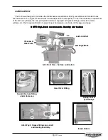
At the top of the head, the saw blade runs in a protective channel as shown below. Grip the blade at each
end of this channel and twist the blade teeth down past the channel and slide the blade forward. Let the blade
rest on the out feed table, then slide the blade down and out of the carbide guides.
SECTION 3, MAINTENANCE and TROUBLESHOOTING
Blade Tensioner
Carbide Tension Handle
Blade R
Blade R
Blade R
Blade R
Blade Remo
emo
emo
emo
emovvvvval fr
al fr
al fr
al fr
al from T
om T
om T
om T
om Top Blade Channel
op Blade Channel
op Blade Channel
op Blade Channel
op Blade Channel
Summary of Contents for S-23H
Page 1: ...I N B A N D S A W T E C H N O L O G Y OPERATIONS MAINTENANCE M A N UA L ...
Page 3: ...THIS PAGE INTENTIONALLY LEFT BLANK ...
Page 6: ...SECTION 1 INSTALLATION SECTION 1 INSTALLATION ...
Page 7: ...SECTION 1 INSTALLATION ...
Page 12: ...SECTION 2 OPERATING INSTRUCTIONS SECTION 2 OPERATING INSTRUCTIONS ...
Page 13: ...SECTION 2 OPERATING INSTRUCTIONS ...
Page 19: ...THIS PAGE INTENTIONALLY LEFT BLANK ...
Page 20: ...SECTION 3 MAINTENANCE AND TROUBLE SHOOTING SECTION 3 MAINTENANCE AND TROUBLE SHOOTING ...
Page 21: ...SECTION 3 MAINTENANCE AND TROUBLE SHOOTING ...
Page 28: ...Pg 3 17 S23H SERVICE RECORD NOTES DATE SERVICED BY COMMENTS ...
Page 29: ...THIS PAGE INTENTIONALLY LEFT BLANK ...
Page 30: ...SECTION 4 ELECTRICAL SYSTEM SECTION 4 ELECTRICAL SYSTEM ...
Page 31: ...SECTION 4 ELECTRICAL SYSTEM ...
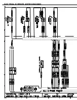
Page 35: ...ELECTRICAL SCHEMATIC WIRING DIAGRAMS ...
Page 36: ......
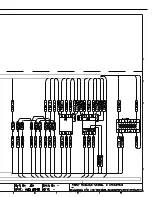
Page 37: ...ELECTRICAL SCHEMATIC WIRING DIAGRAMS ...
Page 38: ......
Page 39: ...THIS PAGE INTENTIONALLY LEFT BLANK ...
Page 40: ...SECTION 5 HYDRAULIC SYSTEM SECTION 5 HYDRAULIC SYSTEM ...
Page 41: ...SECTION 5 HYDRAULIC SYSTEM ...
Page 43: ...Pg 5 28 S22 23H CYLINDER ASSEMBLIES Piston assemblies Gland assemblies ...
Page 44: ...Pg 5 29 S22 23H HYDRAULIC SCHEMATIC and PLUMBING DIAGRAM ...
Page 45: ...Pg 5 30 S22 23H ...
Page 46: ...SECTION 6 MECHANICAL ASSEMBLIES SECTION 6 MECHANICAL ASSEMBLIES ...
Page 47: ...SECTION 6 MECHANICAL ASSEMBLIES ...
Page 48: ...Pg 6 31 S23H 2001a GUIDE ARM CARBIDE ASSEMBLIES SECTION 6 MECHANICAL ASSEMBLIES ...
Page 49: ...Pg 6 32 S23H 2001a BLADE DRIVE ASSEMBLY ...
Page 51: ...Pg 6 34 S23H 2001a HM4A GEAR BOX ASSEMBLY ...
Page 52: ...Pg 6 35 S23H 2001a IDLERWHEEL ASSEMBLY 01 2345 1 345 1 6 7809 849 59 9 3 01 1 ...
Page 53: ...Pg 6 36 S23H 2001a BLADE BRUSH ASSEMBLY ...
Page 54: ...Pg 6 37 S23H 2001a COUNTER BALANCE SPRINGASSEMBLY ...
Page 55: ...Pg 6 38 S23H 2001a PIVOT LINK ASSEMBLY ...
Page 56: ...Pg 6 39 S23H 2001a 0 1 Pivot link parts list ...
Page 57: ...Pg 6 40 S23H 2001a FRONTVISE ASSEMBLY ...
Page 58: ...Pg 6 41 S23H 2001a HYDRAULIC POWER PACK ...
Page 61: ...THIS PAGE INTENTIONALLY LEFT BLANK ...
Page 62: ...SECTION 7 OPTIONAL ASSEMBLIES SECTION 7 OPTIONAL ASSEMBLIES ...
Page 63: ...SECTION 7 OPTIONAL ASSEMBLIES ...
Page 64: ...Pg 7 45 S23H SECTION 7 OPTIONAL ASSEMBLIES WORK STOP ...
Page 67: ...Pg 7 48 S23H 30O MITRE CUTTING ...
Page 68: ...SECTION 8 SPECIFICATIONS SECTION 8 SPECIFICATIONS ...
Page 69: ...SECTION 8 SPECIFICATIONS ...
Page 71: ...Pg 8 50 S23H LAYOUT DRAWINGS ...
Page 72: ...Pg 8 51 S23H ...
Page 73: ...THIS PAGE INTENTIONALLY LEFT BLANK ...
Page 74: ...SECTION 9 WARRANTY SECTION 9 WARRANTY ...
Page 75: ...SECTION 9 WARRANTY ...


