background image

7

14

 104

Use and maintenance manual DM-1215

Rotation axis control

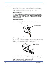
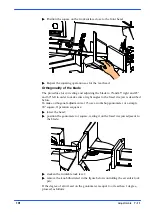
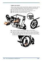
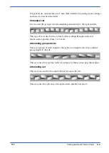
Pulleys must be adjusted in their coplanarity. The adjustment is aimed at ensuring
the belt rotation, keeping approx. 4 mm of distance from the point of the belt
teeth to the pulley machined surface. This prevents an early wear of the belt.

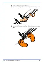
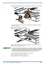
Slacken the blade tension and open the cutting head cover;

slacken the grub screw and, using a mallet, tap the shaft in or out;

finally, close the cover and set the blade in motion;

check the distance, as shown in the picture;

4 mm

if necessary, repeat the operation till getting the correct position.

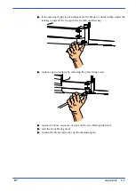
Rear flywheel alignment is closely linked to adjustment of the front flywheel.

Adjust by loosening all pulley locking screws and moving the pulley manually
inwards or outwards according to the distance of the blade from the pulley
machined surface. Tighten the screws again and check the coplanarity making
the belt turn a few times.

Summary of Contents for DM-1215

Page 1: ...USE AND MAINTENANCE MANUAL YEAR OF MANUFACTURE ______________ DM 1215 EN ...

Page 2: ......

Page 3: ... that the bandsawing machine Machine Type SAWING MACHINE Machine model DM 1215 Serial number Year of manufacture is in specification with the following directives EEC MACHINES DIRECTIVE 2006 42 CE S EN 16093 2017 DIRECTIVE 2014 30 UE EMC S EN 50370 1 2005 Emission S EN 50370 2 2003 Immunity Responsible of a Technical File Walter Di Giovanni c o MEP SPA Via Enzo Magnani 1 61045 Pergola PU ITALY Per...

Page 4: ......

Page 5: ...y devices 3 5 Reference standards 3 5 Protection against accidental contact with the blade 3 6 Electrical equipment 3 6 Emergency devices 3 7 Noise level of the machine 3 8 Noise level measurement 3 8 Noise level values 3 8 Vibration emission 3 9 Electromagnetic compatibility 3 9 Machine installation 4 1 Packaging and storage 4 1 Anchoring the machine 4 4 Minimum requirements 4 4 Check list 4 5 Co...

Page 6: ...agrams 6 2 D2 Letter codes used to designate the type of component 6 4 Standardised Wiring Diagrams 6 7 Front flywheel assembly 6 25 Motor flywheel assembly 6 28 Cutting head cover 6 31 Vice assembly 6 33 Base assembly 6 35 Control panel 6 37 Fixed work table and turntable 6 39 Cylinder unit 6 42 Laser and lamp group 6 44 Adjustments 7 1 Vice 7 1 Vice play adjustment 7 1 Cutting head 7 3 Blade ten...

Page 7: ...ndard machine 9 1 Choice of blade 9 3 Saw tooth pitch 9 3 Cutting speed and downstroke speed 9 4 Types of swarf 9 4 Lubricant coolant fluid 9 5 Blade structure 9 6 Blade types 9 6 Conventional rake 9 7 Positive rake 9 7 Variable pitch 9 7 Variable pitch blades with 0 cutting angle 9 8 Variable pitch with positive rake from 9 to 10 degrees 9 8 Set 9 8 Standard or splayed set 9 8 Undulated set 9 9 A...

Page 8: ...8 Troubleshooting blade and cutting problems 10 1 Troubleshooting machine faults 10 8 Accessory Installation 11 1 Blade 11 1 Roller table 11 1 Discharge side roller table adapter with support 11 2 ...

Page 9: ...uct which will give effective and faithful service for many years especially if the instructions contained in this use and maintenance manual are carefully followed This cutting machine has been designed and made specifically for cutting metallic materials Machine presentation Functioning is Manual Gravity feed After having checked the material in the cutting vice the operator must hold the cuttin...

Page 10: ...n bar kg 70 900 When choosing the cutting tool if its dimensions do not correspond to those included in the Rated size section check that the dimensions at least fall within the admissible max min specifications RATED ELECTRICAL POWER Head spindle motor kW 2 2 Electric coolant pump motor kW 0 15 x 2 Max installed power kW 2 5 WORKING PRESSURE Working pressure blade tensioning detensioning kg 900 7...

Page 11: ...tions with shaft oil seal Conforming to CEI norms publication IEC 34 of 01 07 1985 Example of class F insulation in air cooled machines at an ambient tempera ture of 40 C according to CEI 2 3 and IEC 85 the allowable overtempera ture is 100 C where 100 C represents the allowable DT The machine is supplied with a 2 4 pole three phase motor giving 2 band saw speeds 1ª speed 4 poles 40 mt min 2ª spee...

Page 12: ...1 4 12 Use and maintenance manual DM 1215 Dimensions MACHINE INSTALLED Work table height mm 870 Weight Kg 695 1300 2000 2000 PACKED WEIGHT Wooden cage and pallet Kg 100 Wooden pallet Kg 30 ...

Page 13: ...e towards a full understanding of how the machine works which is described in detail in the chapter 5 this chapter deals with the main units and their locations CUTTING HEAD CONTROL PANEL VICE TURNTABLE BASE ÓÓÓÓÓÓÓ ÓÓÓÓÓÓÓ ÓÓÓÓÓÓÓ ÓÓÓÓÓÓÓ ÓÓÓÓÓÓÓ ÓÓÓÓÓÓÓ ÓÓÓÓÓÓÓ 2 ...

Page 14: ... performs a cutting sequence controlled by the cutting head recall spring and the hydraulic brake Motor Head joint pivot Blade guide heads Blade guide head plate Handwheel Transmission box Vice The vice is the unit that clamps the workpiece in place during cutting it consists of a vice support commonly known as a lead nut fixed to the work table and a lead screw with a slideway on which the mobile...

Page 15: ...fted to 0 OFF which automatically cuts off the electrical supply Control panel Main switch Panel fastened by screws Fixed work table and turntable Both the fixed work table and turntable are made from cast iron The turntable constitutes the fulcrum of the cutting head and the machine s cutting surface while the fixed table supports the turntable by means of a 420 mm diameter roller bearing preload...

Page 16: ...ank via the tank cover and a swarf collection drawer An electric pump is housed inside the tank which draws the clean fluid from the filter system Tank cover Swarf collection drawer Electric pump housing Lubricant coolant tank Coolant spray gun On the right side there is the refrigerant fluid gun and the removable shaving collector drawer ...

Page 17: ...The instructions warnings and accident prevention standards in this manual must be respected without question by all those concerned The following definitions are those provided for by EEC MACHINES DIRECTIVE 2006 42 CE Danger zone any zone in and or around a machine in which the presence of a person constitutes a risk for the safety and health of that person Person exposed any person finding himse...

Page 18: ...oiding any blinding light concentrations Reference standard ISO 8995 89 Lighting in work environments CONNECTIONS Check that the power supply cables and pneumatic feed systems comply with the maximum machine absorption values listed in the Machine Specification tables replace if necessary EARTHING The installation of the earthing system must comply with the requirements set out in EN STANDARD 6020...

Page 19: ...ed Always disconnect the power supply to the machine before carrying out any maintenance work whatsoever including in the case of abnormal op eration of the machine Before starting cutting operations support the material at both ends of the machine using the support arm standard or OPTIONAL acces sories such as the feed and discharge roller tables shown in the diagram below Before removing the dev...

Page 20: ... is cutting Do not use blades of different sizes to those recommended in the ma chine specifications When cutting very short pieces make sure that they are not dragged be hind the support shoulder where they could jam in the blade When using the pneumatic vice check that the jaws move right up to and effectively clamp the workpiece as the maximum travel is only 6 mm and check that the clamping pro...

Page 21: ...ectromagnetic Compatibility EEC Directive No 2014 35 EU known as Low voltage directive EN 13898 2003 A1 2009 Machine tools Safety Sawing machines for cold metal EN ISO 12100 2010 Safety of machinery General principles for design Risk assessment and risk reduction HEALTH AND SAFETY AT WORK EEC Directive No 80 1107 83 477 86 188 88 188 88 642 for the protection of workers against risks caused by exp...

Page 22: ... 55 art 108 4 hinged protective cover over blade fitted with removable closing devices 5 blade guide plates completely covering the blade teeth 5 2 1 4 3 5 2 1 3 Electrical equipment In accordance with Italian standard CEI EN 60204 1 2010 derived from European Standard EN 60204 1 2010 Access to electrical control panel limited by screws and panel lock device allowing panel to be opened only after ...

Page 23: ...5 1 Emergency stop a non return mushroom head pushbutton colour red on yellow background is located on the control panel of the machine To release the pushbutton the actuator must be rotated 45 After the emergency situa tion has been resolved the machine must be reset 2 Automatic thermal magnetic cutout switch with thermal magnetic relay the machine auto switch located on the control panel has two...

Page 24: ... of energy expressed in dBA as that actually fluctuating over the same period of time This calculation is made automatically by the integrator noise meter The measurements are taken every 60 seconds in order to obtain a stabilised value The reading stays on the display for a sufficient time to enable a reading to be taken by the operator Measurements are taken by holding the instrument at approxim...

Page 25: ...nt that is contaminated by disturbances of defined magnitude The following text contains a list of the applied standards and the results of the electromagnetic compatibility testing of machine model DM 1215 Test report no 170201 Emissions EN 61000 6 4 2002 Electromagnetic Compatibility EMC Generic standard regarding emissions Part 6 4 Industrial Environment EN 55011 1999 Industrial scientific and ...

Page 26: ...ity EMC Generic standard on immunity Part 6 2 Industrial Environment EN 50370 2 2003 Electromagnetic compatibility EMC Product family standard for machine tools Part 2 Immunity The EUT is deemed to fulfil the immunity requirements without testing because it contains no electonic control circuitry ...

Page 27: ... with straps and heat shrink plastic 2 on a pallet with straps heat shrink plastic and a wooden crate In both cases for correct balancing the machine must be handled using a fork lift truck inserting the tines at the points indicated by the arrows using the reference marks on the crate itself Before carrying out lifting operations make sure that the weight of the ma chine as indicated on the crati...

Page 28: ...k wrapped must not be stacked two high and machines pallettized and crated must not be stacked three high To install the machine first remove the packing paying particular attention not to cut any electric wires or hydraulic hoses if necessary use pliers a hammer and a cutter Open crate in the illustrated order Attention Attention ...

Page 29: ...hrink covering 4 remove the straps 5 remove nails from pallet securing planks and remove planks 6 remove the front panel and insert fork tines To locate the machine in the workplace the machine dimensions and necessary operator working space including the spaces laid down in safety standards must be taken into account ...

Page 30: ...g the machine BASE ÏÏÏÏÏÏ ÏÏÏÏÏÏ ËË ËË Minimum requirements For the machine to function correctly the room in which it is to be installed must satisfy the following requirements power supply voltage frequency refer to the values on the rating plate working pressure MA version not less than 6 Bar and not greater than 8 Bar temperature of machine location from 10 to 50 C relative humidity not more t...

Page 31: ...pped with the blade minimal lubrication kit n Electronic speed control inverter 15 to 100 mt min n Tank for the refrigerant liquid made in the pedestal with a pair of electrical pumps for the refrigeration and lubrication of the belt and shavings drawer This can be replaced by a motorised shavings evacuator optional n Rotating top mounted on a roller bearing with a diameter of 420mm pre loaded wit...

Page 32: ... GND R L1 When using systems with a neutral wire special care must be taken when con necting the blue neutral wire in that if it is connected to a phase wire it will dis charge the phase voltage to the equipment connected for voltage phase neutral Insert the plug in the socket ensuring that the mains voltage is the same as that for which the machine has been setup VOLT VOLT Power up machine by rot...

Page 33: ...lever if all the above operations have been carried out correctly the blade motor will start up and the blade will start rotating Ensure that the blade moves in the correct direction as shown in the above figure If it does not simply reverse two of the phase wires on the ma chine power supply input The sawing machine is now ready to start the work for which it was designed Chapter 5 provides a det...

Page 34: ......

Page 35: ...buttons and other components on the control panel Description of the control panel The components of the DM 1215 control panel are shown in the diagram below Each arrow has a number which corresponds to the descriptions that follow 115 15 35 55 75 95 5 1 2 4 3 6 7 8 9 ÓÓÓÓÓÓÓ ÓÓÓÓÓÓÓ ÓÓÓÓÓÓÓ ÓÓÓÓÓÓÓ ÓÓÓÓÓÓÓ ÓÓÓÓÓÓÓ ÓÓÓÓÓÓÓ 5 ...

Page 36: ... adjust oil flow in the hydraulic cylinder to determine the cutting head descent speed 6 AUTOMATIC THERMAL MAGNET CUTOUT WITH MINIMUM VOLTAGE RELAY AND HATCH LOCKING DEVICE The machine is provided on the right of the control panel with a main switch with a locking device which when set in the ON position 1 powers up the machine by resetting the minimum voltage relay and the blade motor thermal mag...

Page 37: ...the machine Also the grip on the head control lever enables the operator to achieve a firm grip in order to start up band saw rotation by pressing the mi croswitch start lever located in the handle itself Clamping the work piece in the vice In the basic version the work piece is clamped in the vice by rotating the opening closing handwheel in a clockwise anticlockwise direction as shown each time ...

Page 38: ...n 2 3 mm of the workpiece using the hand wheel Rapid vice translation For angled cuts the vice may be slid to the left or right along the prismatic guide Release the locking lever illustrated in the figure below Position the vice to the right or left and lock the lever Width of cut The machine is fitted with protections which protect the entire blade stroke leaving exposed only the part of the bla...

Page 39: ...o lock the head slide Preliminary check list for cutting operation To guarantee complete safety during cutting cycles the operator should work through a check list of the entire apparatus checking blade tension that the blade guide head bracket is locked in the correct position that the cutting angle is correct and that the surface to be cut is blocked that the work piece is properly clamped in pl...

Page 40: ...t Manual operating cycle Sequence of the cutting operations power up the machine by turning the main switch Position the workpiece in the vice and calculate the length of cut using the measuring rod for cuts to measure Clamp the workpiece in the vice Select the cut using the Inverter 115 15 35 55 75 95 Grip the head control lever and start the blade rotating by pressing the mi ...

Page 41: ...e downstroke speed of the head is manually con trolled by the operator The motor starts up and sets the blade in rotary motion the lubricant coolant pump starts up at the same time At the end of the cutting operation the head can be raised Remove the piece from the vice ...

Page 42: ...ead return spring using the appropriate crank so that the first turn is aligned with the Semi automatic Dynamic cycle notch Set the head downstroke speed on the hydraulic panel located below the ma chine control panel according to the characteristics of the material to be cut Grip the head control lever and move the blade in the proximity of the mate rial to be cut when you reach a distance of app...

Page 43: ... the vice is positioned to the left of the 0 cutting slot slacken the turntable lock release lever Pull the eccentric pin knob towards you 0 reference stop and rotate slightly to raise it The 0 45 and 60 reference stops for cuts to the left and the 45 reference stop for cuts to the right facilitate rapid head positioning during turntable rota tion However the eccentric pin is only correctly positi...

Page 44: ...ition to avoid blade collision with the moving jaw on the clamp Relock the turntable lock release lever Make the cut in the required operating mode following the preliminary safe ty instructions set out in this chapter Angled cuts 60 to the left Undo the bush on the 45 left reference stop as illustrated in the figure be low using a 36 mm wrench Remove the 45 reference stop slacken the turntable lo...

Page 45: ...til it is positioned at the required angle as indicated by the graduated scale on the turntable relock the turntable lock release lever Before cutting remove the lever from the front head support and replace it with the grub screw in the accessory pack Make the cut in the required operating mode following the preliminary safe ty instructions set out in this chapter ...

Page 46: ...ollision with the blade downstroke Following the same procedure described above for 45 cuts to the left now position the head for 45 cuts to the right slacken the turntable lock release lever pull the eccentric pin knob towards you 0 reference stop and rotate slightly to raise it rotate the head from right to left till reaching the wished cant which is dis played by the grading on the rotating pla...

Page 47: ...nded to help in identifying the location of the various components making up the machine giving information useful in carrying out repair and maintenance operations This chapter will also enable the user to order replacement parts with no risk of misunderstanding as all parts are given codes ÓÓÓÓÓÓÓ ÓÓÓÓÓÓÓ ÓÓÓÓÓÓÓ ÓÓÓÓÓÓÓ ÓÓÓÓÓÓÓ ÓÓÓÓÓÓÓ ÓÓÓÓÓÓÓ 6 ...

Page 48: ...ay in which they have been drawn up Each sheet of the project contains a box which gives the following information The numbers indicate the columns into which the entire drawing is divided Indications of the date production started Identification of the designer Identification of the Reference Standard Indications of the model of machine Indication of the page number MARIO ROSSI ...

Page 49: ...er after the dot identifies the column on that page example 11 8 indicates that the wire contin ues on page no 11 in column 8 This symbol identifies the wire with its relative number and colour The pages following the wiring diagrams contain the following lists 1 components list list of all components and terminals list list of all the ter minals with the following information in house article cod...

Page 50: ...04 1 D2 Letter codes used to designate the type of component LETTER TYPE OF COMPONENT EXAMPLES IDENTIFICATION OF THE APPLIANCE A Complex units Laser Maser Regulator A B Transducers converting a non electrical signal to an electrical signal and vice versa Transistor amplifier IC amplifier Magnetic amplifier Valve amplifier Printed circuit board Drawer Rack AD AJ AM AV AP AT AR C Capacitors C D Bina...

Page 51: ...ll or nothing timed relays timers KA KL KM KP KR KT L Inductors reactors Inductor Stop coil Reactor I M Motors M N Analogue intgrated circuits Operational amplifiers Hybrid analog digital appli ances N P Measurement equipment test de vices Indicator recorder and inte grator measurement devices Signal generators P Q Power circuit switching appliances Automatic switch Engine saver switch Knife switc...

Page 52: ...pipes semiconductors Electronic pipe Gas discharge pipe Diode Transistor Thyristor V W Transmission lines wave guides antennas Conductor Cable Bar Wave guide Wave guide directional cou pler Dipole Parabolic antenna W X Terminals sockets plugs Connector bar Test plug Plug Socket Terminal connector band XB XJ XP XS XT Y Electrically operated mechanical appliances Electromagnet Electromagnetic brake ...

Page 53: ...6 7 52 Diagrams exploded views and replace Standardised Wiring Diagrams ...

Page 54: ...6 8 53 Use and maintenance manual DM 1215 ...

Page 55: ...6 9 54 Diagrams exploded views and replace ...

Page 56: ...6 10 55 Use and maintenance manual DM 1215 F6 F7 F8 F3 F4 F5 RT4 ...

Page 57: ...6 11 56 Diagrams exploded views and replace F1 F2 F9 ...

Page 58: ...6 12 57 Use and maintenance manual DM 1215 S4 KSTO S8 S4 K01 ...

Page 59: ...6 13 58 Diagrams exploded views and replace KSTO KSTO RT4 ...

Page 60: ...6 14 59 Use and maintenance manual DM 1215 F10 F11 HL1 GD1 F12 HL2 SL1 SL1 F13 SLM YV1 S V SPRAY MIST SYSTEM ...

Page 61: ...6 15 60 Diagrams exploded views and replace ...

Page 62: ...6 16 61 Use and maintenance manual DM 1215 ...

Page 63: ...6 17 62 Diagrams exploded views and replace ...

Page 64: ...6 18 63 Use and maintenance manual DM 1215 ...

Page 65: ...6 19 64 Diagrams exploded views and replace ...

Page 66: ...6 20 65 Use and maintenance manual DM 1215 ...

Page 67: ...6 21 66 Diagrams exploded views and replace ...

Page 68: ...6 22 67 Use and maintenance manual DM 1215 ...

Page 69: ...6 23 68 Diagrams exploded views and replace ...

Page 70: ...6 24 69 Use and maintenance manual DM 1215 ...

Page 71: ...6 25 70 Front flywheel assembly ...

Page 72: ...EPUSHER BEARING ECCENTRIC PIN SH230 6 000 010 4021 PIASTRA REGOLAZIONE SLITTA LARDO NE SH 320 330 332 H 14A GIB SLIDE ADJUSTMENT PLATE SH 320 330 2 000 010 4516 SUPPORTO TESTINA ANTERIORE FRONT HEAD SUPPORT 6 000 010 4526 SUPPORTO RULLI TESTINA GUIDALAMA MOBILE ROLLER SUPPORT GUIDALAMA MOBILE HEAD 6 000 010 4818 SUPPORTO LEVA COMANDO TESTA HEAD CONTROL LEVER SUPPORT 6 000 010 7203 DADO M6 010 7203...

Page 73: ...1 000 016 3137 PROTEZIONE LAMA ANTERIORE FRONT BAND GUARD 1 000 016 3621 STAFFA DI FERMO SH 332 382 LOCKING BRACKET SH 332 382 1 000 019 5370 FASCETTA LEGRAND ART 31900 LEGRAND CLAMP ART 31900 1 000 022 0369 CONNETTORE PER BOBINA U2 E TEN SIONATORETRSA 3T 00 SH 420 282 292 332 CONNECTOR F U2 COIL AND TENSIONER 1 000 022 2152 TENSIONATORE ELETTRONICO TR SA 3T 00 ELECTRONIC TENSIONER TRSA 3T 00 1 00...

Page 74: ...6 28 73 Use and maintenance manual DM 1215 Motor flywheel assembly ...

Page 75: ... SH 1 000 010 1884 CERNIERA X PROTEZIONE VW 18CFA 49 CH5 PROTEC HINGE VW 18CFA 49 CH5 1 000 010 2180 ALBERO RIDUTTORE TAGLIA 75 SH 332 DRIVE SHAFT 1 000 010 2208 PORTASPAZZOLA PULILAMA SH 260 282 320 SH 332 BAND BRUSH HOLDER 1 000 010 7010 ANELLO SEEGER 0 45 010 7010 0 45 SEEGER RING 1 000 010 7111 CHIAVETTA 8 X 7 X 32 010 7111 8 X 7 X 32 KEY 1 000 010 7226 DADO AUTOBLOCCANTE M6 010 7226 M6 SELF L...

Page 76: ...CON CHIAVEFR993 D10 SH 230 NC HS SAFETY SWITCH FR993 D10 SH 230 NC HS 1 000 025 0075 CUSCINETTO 32009X BEARING 32009X 2 000 025 0089 CUSCINETTO 3307 A2RS BEARING 3307 A2RS 1 000 025 0225 ANELLO TENUTA OR 171 68 26 O RING 171 68 26 1 000 025 0238 ANELLO DI TENUTA OR 149 44 45X3 53 O RING 149 44 45X3 53 1 000 025 0275 ANELLO DI PROTEZIONE NILOS 32009X NILOS GUARD RING 32009X 2 000 025 0552 SPAZZOLA ...

Page 77: ...6 31 76 Cutting head cover ...

Page 78: ...A DIAM 8 X 30 CYLINDRICAL PIN DIAM 8 X 30 2 000 010 7830 VITE BUTON 5 X 10 5 X 10 BUTON SCREW 2 000 010 8922 VITE TE 12 X 90 12 X90 TE SCREW 2 000 016 0956 COPERCHIO ARCHETTO N T SH 382 BOW COVER SH 382 2 000 016 1250 PIASTRINO FIX INTERRUTTORE COPERCHIO PLATE FIXING BOW COVER SAFETY SWITCH 2 000 016 3366 CARTER POSTERIORE TRAVE SH 382 REAR CARTER 2 000 019 5370 FASCETTA LEGRAND ART 31900 LEGRAND ...

Page 79: ...6 33 78 Vice assembly ...

Page 80: ...OLIATORE A SFERA DIAM 8 OIL FILLER DIAM 8 2 000 010 2372 CHIOCCIOLA BRONZO 45 SH 260 270 280 281 282 292 320 332 422 452 SCREW NUT 45 1 000 010 7203 DADO M6 010 7203 M6 SCREW NUT 010 7203 7 000 010 7410 GRANO VCE PUNTA CILINDRICA 8X16 8X16 CYLIND POINT VCE GRUB SC REW 1 000 010 7456 GRANO VCE PUNTA CONICA 8 X 16 010 7456 8 X 16 CONICAL POINT VCE GRUB SC REW 5 000 010 7463 GRANO VCE PUNTA CONICA 6 ...

Page 81: ...6 35 80 Base assembly ...

Page 82: ... 2 FAIRLEADS 12 INC M M 2 1 000 028 0010 PISTOLA SH TI ART 8966 COOLANT PISTOL SH TI 8966 1 000 028 0121 RACCORDO 3 8 17 CL 2601 JOINT 3 8 17 CL 2601 2 000 028 0260 ELETTROPOMPA V 220 240 380 415 50HZSPV33 ELECTROPUMP 230 400 50 HZ SPV33 1 000 028 0391 TUBO LOOC LINE SPD ART 69540 3 4 LOOC LINE HOSE SPD ART 69540 3 4 1 000 028 0396 UGELLO 0 20 SPD FP50 11B50 NOZZLE 0 20 SPD FP50 11B50 1 000 028 04...

Page 83: ...6 37 82 Control panel ...

Page 84: ...0 022 0234 PRESSACORDONE 3246 NERO PG 13 5 CORD PRESSER PZ 1 000 022 0244 CONTRODADO 3217B GRIGIO PG 13 5 LOCK NUT 3217B GREY PG 13 5 PZ 1 000 022 0249 DADO POLIAMIDE HUMMEL DIAM 16 POLYAMIDE HUMMEL NUT 0 16 PZ 1 000 031 3254 PANNELLO COMANDI SUPERIORE DM 12 15 UPPER CUTTING CONTROL PANEL DM 12 15 PZ 1 000 031 3259 PANNELLO COMANDI INFERIORE DM 12 LOWER CONTROL PANEL DM 12 PZ 1 000 034 1169 MANOPO...

Page 85: ...6 39 84 Fixed work table and turntable ...

Page 86: ... 010 0352 GHIERA AUTOBLOCCANTE 35X1 5 CN TI SH FC SELF LOCKING RING NUT 35X1 5 CN TI SH FC 1 000 010 0370 GHIERA 5S 30X1 5 SH 200 260 280 282 292 332 RING NUT 5S 30X1 5 SH200 260 280 1 000 010 0424 GRANO PUNTA PIANA 12X170 SH 320 332 GRUB SCREW 12X170 SH 320 1 000 010 0425 GRANO PUNTA PIANA 12X190 SH 320 332 GRUB SCREW 12X190 SH 320 1 000 010 0426 GRANO PUNTA PIANA 12X135 SH 320 332 GRUB SCREW 12X...

Page 87: ... 010 7975 VITE TE 10 X 25 010 7975 TE 10 X 25 SCREW 010 7975 1 000 010 7988 VITE TE 12 X 60 TE 12 X 60 SCREW 1 000 010 8982 VITE TCEI M8 X 140 TCEI 8 X 140 SCREW 1 000 010 9074 GRANO VCE PUNTA PIANA 10 X 20 10X20 FLAT POINT GRUB SCREW 1 000 010 9074 GRANO VCE PUNTA PIANA 10 X 20 10X20 FLAT POINT GRUB SCREW 1 000 016 0131 CARTER TRUCIOLI PER PIANO GIRE VOLESH 320 332 ROTATING TABLE SWARF COVER SH 3...

Page 88: ...6 42 87 Use and maintenance manual DM 1215 Cylinder unit ...

Page 89: ... GROOVER M10 WASHER GROOVER M10 1 000 010 7645 RONDELLA GROOVER M8 M8 SPRING WASHER 1 000 010 7894 VITE TCEI 8 X 25 010 7894 TCEI 8 X 25 SCREW 010 7894 1 000 010 7924 VITE TCEI 10 X 30 010 7924 TCEI 10 X 30 SCREW 010 7924 1 000 010 7976 VITE TE 10 X 30 010 7976 TE 10 X 30 SCREW 010 7976 1 000 016 0296 STAFFA ESTERNA CILINDRO SH OUTER CYLINDER BRACKET SH 1 000 025 0930 CUSCINETTO 51100 BEARING 5110...

Page 90: ...6 44 89 Use and maintenance manual DM 1215 Laser and lamp group ...

Page 91: ...000 016 2778 STAFFA LAMPADA LED BRACKET LED LAMP 1 000 016 3620 STAFFA SUPPORTO LASER LAM PADA DM 1215 LASER LAMP SUPPORT BRACK ET 1 000 022 1191 LASER MOD 5OEM 24V OTTICA ARIGA CON M8 MASCHIO PANNEL LO SENZA CAVO LASER MOD 5OEM 24V 1 000 022 3255 FARO LED 4 2W 16 36 VCC 330LM LED LIGHT 4 2W 16 36 VCC 330LM 1 000 ...

Page 92: ......

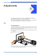
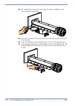
Page 93: ...ny play that develops between the slideway and the slide gib on the vice must be compensated by adjusting the grub screws regulating the distance between the gib and the lead screw proceeding as follows slacken all the locknuts on the grub screws using a hexagonal key to hold the screws still open the vice to its full extension ËË ËË adjust the slight pressure exerted by the grub screws on the gib...

Page 94: ...nal key close the vice until two more grub screws are in the same position as the first two previously repeat the operation on the gib grub screws on all the slideway grub screws at the end of the operation use the handwheel to move the slideway back and forth identifying the zones where the grub screws exert greater pressure on the gib ...

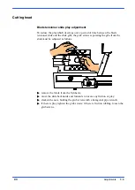
Page 95: ...d the slide gibs the grub screws separating the gibs from the slide must be adjusted as follows remove the blade from the flywheels move the slide backwards and forwards to locate any friction or play slacken the nuts holding the grub screws with a hexagonal pipe wrench if there is play tighten the grub screws if there is friction rubbing loosen the grub screws ...

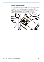
Page 96: ... FTCI End Run Cutting Head Backwards points and FCTA End Run Cutting Head Forwards It is possible to set the end cut FCTA point as illustrated Loosen the end run support screw fasteners and move it forward and back ward in the slots to near it or distance it from the contact point Tighten the screws when the optimal position has been obtained ...

Page 97: ...flexure caused by the vertical action of the cutting force These buttons are fitted on both the front and rear heads and need no adjustment Blade steady button Blade guide head Blade guide plates The plate contact points feature widia inserts which guide the blade longitudinal ly A small amount of play must exist between the plates and blade to ensure that the blade runs smoothly and perpendicular...

Page 98: ...ion using the handwheel open the front blade guard by undoing the fixing screw and rotating it as illus trated in the figure below wear protective gloves when making this adjustment make sure there is a small amount of play between the blade and guide plate inserts ...

Page 99: ...un smoothly adjust the locking torque of the two grub screws with an Allen key replace any worn plates by removing the plate fixing screw repeat the above sequence of steps on the rear blade guide head refit the front blade guard tension the blade and power up the machine again ...

Page 100: ... operator safety and extend the tool s service life The cutting tool should in any case be replaced when poor cutting performance starts to affect productivity The tool changeover procedure is described as follows disconnect the machine from the power supply slacken the blade tension using the handwheel open the cutting head cover by unscrewing the two knobs and hooking it onto the galvanised leve...

Page 101: ...guide head make sure the back of the blade is facing the flywheel stop and that the teeth along the lower part of the blade are inclined towards the head pivot Make sure there is a small amount of play between the blade and guide plate inserts repeat the above sequence of steps on the rear blade guide head fit the blade on the flywheels and remount the front and rear blade guards close the cutting...

Page 102: ...acent to the blade resting on the work surface Position the square on the cleaned work surface and rest it against the blade close to the right vice jaw at a point where the blade teeth do not prevent con tact Slacken the TCEI head fixing screw A and adjust the two grub screws B if the blade touches the square at its lower part If the point of contact is at the upper part slacken the TCEI screw A ...

Page 103: ...at right angles to the fixed vice jaw is described below To make orthogonal adjustments at 0 use a workshop goniometer or a simple 90 square Operation sequence lower the head position the goniometer or square resting it on the fixed vice jaw adjacent to the blade slacken the turntable lock lever remove the knob illustrated in the figure below controlling the eccentric lock pin If the degree of err...

Page 104: ...ccentric pin tighten down the grub screw and remount the knob lock the turntable using the lever To adjust the 45 and 60 fixed points you will need a workshop goniometer or an instrument that can measure the exact angle of the blade This operation can also be performed to adjust the blade to 45 right since a head angle control pin is also mounted on the left hand side of the work table Operation s...

Page 105: ...his done adjust the depth of the pin inside the turntable until the error is corrected relock the nut while gripping the grub screw If the machine is equipped with optional cutting angle display check that the mechanical zero corresponds to the displayed zero if not contact our techni cal service To adjust the blade to 60 degrees left proceed as described above for a 45 degree angle this time howe...

Page 106: ...lacken the grub screw and using a mallet tap the shaft in or out finally close the cover and set the blade in motion check the distance as shown in the picture 4 mm if necessary repeat the operation till getting the correct position Rear flywheel alignment is closely linked to adjustment of the front flywheel Adjust by loosening all pulley locking screws and moving the pulley manually inwards or o...

Page 107: ...r the safety of other personnel and in the interests of machine productivity check that his own work and that of the other operators of the machine always complies with the relevant safety standards Therefore check that the safety de vices are in position and work perfectly and that personal safety requirements are complied with Ensure that the working cycle is efficient and guarantees maximum pro...

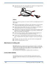
Page 108: ...and those on the product itself General maintenance Daily The daily maintenance operations to carry out on the machine are as follows remove all swarf from the machine preferably with a non fibrous cloth empty the swarf drawer this is located on the right side of the base top up the lubricant coolant level check state of blade wear and replace if necessary check the blade cleaning brush clean and ...

Page 109: ...ular and orthogonal check the precision of the 45 and 60 left stops and the 45 right stop if out of set adjust following the steps indicated in Chapter 7 check the state of the widia inserts and the blade steady button replace if worn or chipped check their positions and adjust if necessary see Chapter 7 thoroughly clean the bottom of the water tank and the electropump filter controls the hydrauli...

Page 110: ...O Glycolube Range 220 IP CT614 FINA Girans transmission box capacity Lt 0 320 Oil for lubricant coolant fluid The oil used for the machine lubricant coolant fluid is CASTROL Syntolin TFX Though there are no specific standards for these types of oils MEP considers that the above product has the best price quality rapport The following oils can also be said to have similar characteristics and are th...

Page 111: ...peeds for which the optional electronic speed controller inverter is necessary When using the DM 1215 it is important to select the correct type of blade for the material to be cut This chapter explains the limitations and specific applica tions of the different types of blades Cutting speed Standard machine The basic version with 4 pole motor is provided with the following range of cutting speeds...

Page 112: ...range 0 5 320 Hz Max transients 150 of electronic speed control rated current for 60 secs Frequency resolution Display 0 1 Hz Analog inputs 0 1 Hz per 100 Hz max Switching frequency Adjustable from 2 2 to 12 Hz max Electronic speed control protection and safety de vices Motor protections Motor protections Galvanic insulation between power and control panel Short circuit protection of available int...

Page 113: ...ooth penetration soft materials aluminium alloys soft bronze etc also require a coarse tooth pitch Saw tooth pitch The choice of teeth per inch therefore depends on various factors the size of the section the hardness of the material workpiece wall breadth Very large dimensions require coarse teeth while small dimensions require finer teeth Whatever the case ensure that there are always at least s...

Page 114: ...s Therefore large section solid or thick walled materials s 5 mm can be cut at high speeds providing there is sufficient swarf removal from the blade thin walled materials such as slim piping or profiles must be cut using low and especially constant downstroke speeds A new blade must be worn in which in effect means lowering the downstroke speed to about half that of normal from 60 to 70 cm2 min o...

Page 115: ... teeth nor the work piece material in the cutting zone overheat Furthermore there must be a sufficient quantity and pressure of lubricant coolant to remove swarf from the cutting zone The lubricant coolant fluid must be of the highest quality in order to prevent tooth abrasion and welding of swarf to the teeth themselves seizing ...

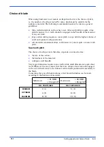
Page 116: ... 1 00 0 12 0 52 0 08 45 50 0 85 0 25 0 30 4 15 6 37 5 00 1 92 64 66 1 07 0 25 0 20 3 75 1 50 9 50 1 15 8 00 67 69 ËËËËË ËËËËË ËËËËË ËËËËË ËËËËË ÊÊÊÊ ÊÊÊÊ ÊÊÊÊ ÏÏÏÏÏ ÏÏÏÏÏ HRC 67 68 HRC 45 50 ËËËËË ËËËËË ËËËËË ËËËËË ÊÊÊÊ ÊÊÊÊ ÊÊÊÊ ÏÏÏÏÏ ÏÏÏÏÏ HRC 65 66 HRC 45 50 TYPE OF BLADE The numbers in the columns indicate the content of the element in the steel Blade types The blades mounted on the DM 1215 ar...

Page 117: ...rge sections and diameters Variable pitch These blades have groups of teeth having different pitches and as a consequence have various tooth dimensions and differing relief angles These are also available in M2 and M42 types with zero and positive rakes The alternation of the different types of teeth helps to prevent vibration and noise Elimination of vibration increases the useful life of the too...

Page 118: ...ing type is the most suitable for cutting large dimension pipes and profiles including large sections as well as for cutting solid sections up to the machine capacity limit Pitches available 3 4 4 6 Set The term set refers to the section of material removed by the blade during the cutting operation i e relating to width of cut and the offset position of the teeth with respect to the blade back Sta...

Page 119: ...f set is used with very fine teeth for cutting thin pipe walls and small section profiles from 1 to 3 mm Alternating grouped sets These are groups of teeth angled to the right one straight tooth then a further group angled to the left This set is used for very fine teeth for cutting very thin sections less than 1 mm Alternating set This set is one tooth to the right followed by one to the left Thi...

Page 120: ...3 4 4 6 4 6 4 6 4 6 4 6 3 4 3 4 3 4 3 4 3 4 3 4 3 4 3 4 3 4 3 4 3 4 3 4 3 4 3 4 60 70 50 60 15 20 15 20 75 90 80 90 25 40 70 80 80 90 S10 10S30 30S50 50S80 80S120 120S230 Dimensions of the cutting section S mm Cutting speed mt min Cutting material Blade pitch Number of teeth per inch sq mt min cut Structural steel Casehardened steel Steel for turning Mild steel High duty cast iron Rolled steel Spr...

Page 121: ...1 845 En 58 E En 56 A En 58 G A 1 A 2 En 36 4360 50 A 3706 1 2 3 En 20 A En 31 1022 1035 1040 1010 1015 1060 1065 5135 5145 4135 3135 4315 8645 W 1 L 6 T 1 1310 316 304 410 309 S D 3 M 13 3310 3315 ASTMA 36 68 52100 Brinell HB HRB Kg mmq 160 170 160 180 150 175 160 180 160 180 180 205 180 200 200 230 190 230 200 225 190 220 150 190 190 230 217 248 217 248 160 200 130 170 150 200 215 240 200 230 16...

Page 122: ...55 080 A 40 080 A 62 1717 CDS 110 708 A 37 708 M 40 735 A 50 534 A 99 817 M 40 311 rodzaj 6 7 BD 2 BD 3 BS 1 304 S 15 304 C 12 316 S 16 317 S 16 XC 18 XC 38 H 1 20 M 5 XC 60 XC 75 40 M 5 XC 42 H 1 25 CD 4 35 NCD 6 50 CV 4 100 C 6 Z 160 CVD 12 Z 200 C 12 55 NCVD 7 Z 2 CN 18 10 Z 6 CN 18 09 Z 3 CN 19 10 Z 12 CNS 25 20 Z 6 CND 17 12 304 S 12 C 15 C 35 C 22 Mn C 28 Mn C 45 C 60 40 Ni Cr Mo 2 40 Ni Cr ...

Page 123: ...cal procedure for solving any problem Troubleshooting blade and cutting problems PROBLEM PROBABLE CAUSE SOLUTION Blade scored or scratched Widia inserts chipped or worn Replace Widia inserts loose or tight Adjust Widia inserts dirty Clean and re adjust correctly Cutting surfaces scored Blade teeth worn Replace blade Head downstroke speed too fast Reduce downstroke speed Cutting speed too slow Incr...

Page 124: ... stroke speeds or clean sur face Cutting speed too high The teeth slide on the materi al without cutting reduce cut ting speed Head downstroke speed too slow The band saw runs over the material without removing it increase downstroke speed Insufficient coolant Check coolant level and clean pipes and jets Incorrect fluid concentration Check and use the correct concentration New blade inserted into ...

Page 125: ... 45 right and left by means of the appropriate screws Perpendicularity of the blade to the work surface Check and realign the blade guide heads then adjust the blade using the appropriate screws so that it is perpen dicular to the work surface Blade tension incorrect Bring pressure up to 60 Bar Blade worn Replace blade Tooth pitch unsuitable Probably a blade with too many teeth per inch is being u...

Page 126: ...e al tered surface areas such as oxides or sand or subcooled inclusions in the section These areas are much hard er than the blade and will cause the teeth to break scrap or clean these materi als Workpiece not clamped The blade may break if the workpiece moves during cut ting check the vice jaws and clamping pressure The blade stops in the cut Cutting pressure too high check and restore to rated ...

Page 127: ...em downwards so as to bring the blade steady buttons up against the back of the blade Sections with large thickness variations The cutting speed and down stroke speed must be chosen to suit the most critical part of the cut Teeth angled in the wrong di rection Fit blade so that teeth point in the right direction Blade run in wrongly When using a new blade the cutting and downstroke speeds must be ...

Page 128: ...ings Workpiece not clamped prop erly The blade may break if the workpiece moves during cut ting check the vice jaws and clamping pressure Widia inserts positioned in correctly Adjust inserts position espe cially the width since blade thickness can exceed the manufacturer s declared tol erance ratings Widia blade steady buttons Can have a milling action on the back of the blade if worn or chipped c...

Page 129: ... of the blade before starting a new job especially for the semi automatic cycle Widia inserts If worn the inserts can score the blade weakening it even to breaking point If the in serts are too far apart the blade will whip striking both the inserts and the material Replace or adjust Insufficient coolant Check coolant fluid level clean pipes and jets Incorrect fluid concentration Check and use the...

Page 130: ... the blade is not correctly tensioned to 60 Bar the pressure contact does not close and the machine is in EMERGENCY state Blade protection cover Check that the closure is cor rect and the limit stop pressed Current drop Check connections on the handgrip switch the blade protection limiter and the pressure gauge on the blade tensioner group BMT not energised Minimum Tension Coil Electrical power su...

Page 131: ... is not kinked or blocked Remove the ob struction Air treatment unit Check that the air treatment group is supplying the pres sure shown on the gauge The CCS optional is not working Minimum voltage relay Check that it is correctly sup plied and not burnt out Selector switch Check connections Replace if defective Lock valve Check for impurities prevent ing correct functioning Re place if defective ...

Page 132: ......

Page 133: ...belt installation instructions Roller table K210 roller table module for feed side 1500 mm K210 roller table for discharge side 1500 6000 mm K210R roller table for discharge side 1500 6000 mm To fit the roller loading platform on the loading side the machine has a bar sup port arm that one end of the roller way can be positioned on and then screwed in place To install the roller loading platform o...

Page 134: ...crews from the right side of the slideway install adaptor fixing the plate to the fixed platform after having removed the bolts and fit the support to the end of the plate using two of the four holes in the upper part of the support leaving the other two free for attaching the roller way Attach the outfeed rolling deck by fixing it with the screws supplied ...

Page 135: ...ng it unsuitable for its intended use or significantly decreasing its value The guarantee shall not apply if the buyer was aware of defects in the product when buying it or if defects were clearly recognizable Regulations by the Italian law shall apply to this article ...

Page 136: ......

Reviews: