


C:\TEMP\ml59101.doc | Revised: 20JUN18 | Page 9 of 39
TROUBLE SHOOTING
Step 1.
Check that the green TRAVEL MODE light is not on. Make sure the park brake is set. Turn the ignition to the “ON”
or “ACC” position. The TRAVEL MODE light should come on. +12 power for the touch panel and MIOMs is routed to the
front MIOM through the system latch in relay assembly.
PROBLEM
SOLUTION
DIAGRAMS
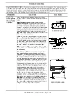
Step 1a. The
green TRAVEL
MODE light is
on with the
ignition off.
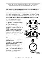
The issue will be at the front air module MIOM. There is
power on the red 6120 wire for pin A1 or the red 6102 wire for
pin D1 of the front MIOM main connector. There should be no
power on these wires with the ignition off. The 6120 wire is
ignition power. The 6102 wire is battery power. If there is
power on the 6120 wire there should also be power on the
6102 wire. If there is no power on the 6120 wire but there is
power on the 6102 wire, the CR1 or CR2 Bosch relay is stuck
on and should be replaced.
8
7 6
5 4
3 2
1
A
B
C
D
FRONT VIEW OF I/O MODULE
CONNECTOR
REFER TO MP84.3180
LINK LIGHT
PIN 1
HWH COMPUTERIZED LEVELING
WARNING!
UNDERSTAND OPERATOR'S MANUAL BEFORE USING. BLOCK FRAME AND TIRES
SECURELY BEFORE REMOVING TIRES OR CRAWLING UNDER VEHICLE.
EMERGENCY
STOP
MODE
TRAVEL
LEVEL
MODE
TRAVEL
RAISE
BRAKE
PARK/
SLOPE
EXCESS
NOT IN
DUMP
AIR
CN1
REFER TO MP84.6195
LINK LIGHT
REFER TO MP84.3180
SYSTEM LATCH
IN RELAYS
SEE MP84.3200
A
B
6120
6101
REFER TO MP84.3060
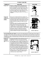
Step 1b. The
green TRAVEL
MODE light is
off. The ignition
is on. The park
brake is set.
If a yellow level light is on, replace the touch panel. If a level
light is not lit, push the “RAISE” or “DUMP” button. If the light
above the button comes on, replace the touch panel. If the
light does not come on, there is a system power or
communication problem between the MIOMs and the touch
panel.
There is a link light on the back of the touch panel and one on
each air manifold MIOM. These lights should be flashing with
the ignition on.
CHECK THAT ALL LINK LIGHTS ARE
FLASHING
.
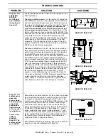
ALL LINK LIGHTS ARE FLASHING –
Check for +12 power
on the red 6120 wire (pin A1) at the front MIOM. If +12 power
is present, replace the MIOM. If +12 power is not present,
there is an issue with the 6120 wire between the front MIOM
and the latch in relay assembly. Check the wire and plug
connections. Fix as necessary.
SOME LINK LIGHTS ARE OFF OR ON STEADY.
There is
most likely a communication issue. There may also be a
power issue for a MIOM or the touch panel. Check for +12
power between wires 6122 (red) and 6230 white at the
MIOMs and touch panel. If +12 power is not present, repair
the harness wires as necessary.
If +12 power is present at all components, unplug the main
connector from the front and rear MIOMs and the 5 pin MTA
connector from the touch panel. At the touch panel, check
resistance between pins 1 and 2, the yellow and green wires,
of the MTA connector. There should be between 55 and 65
Ohms of resistance. If the resistance is not correct, there is an
issue with the harness
There is a 120 OHM resistor between the yellow and green
wires in the harness near the touch panel and the rear MIOM.
If you measure approximately 120ohms, one of the resistors
may be bad or possibly a bad spot in one of the wires.
If resistance measures OK, make sure the yellow and green
wires are properly seated in the connectors. Make sure the
yellow and green wires are in the proper location at all
connectors including the front MIOM.
At the MIOMs, the yellow wire should be on pin A2. The green
wire should be on pin B2. At the touch panel, the yellow wire
should be on pin 1 and the green wire should be on pin 2.
If resistance is OK and the wires are seated properly in the
correct locations, the issue is the touch panel or one of the
MIOMs. There is no good way to test these components. Try
the touch panel first but you may want to order all three parts
and make arrangements to return the unused parts.
8
7 6
5 4
3 2
1
A
B
C
D
FRONT VIEW OF I/O MODULE
CONNECTOR
REFER TO MP84.3180


