


C:\TEMP\ml59101.doc | Revised: 20JUN18 | Page 16 of 39
TROUBLE SHOOTING
PROBLEM
SOLUTION
DIAGRAMS
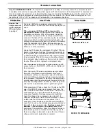
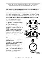
Step 5a. Cont.
If there is no voltage on terminal 3 (red battery wire),
check the fuse for this wire. On older systems the fuse is
close to the compressor. On later models, the fuse is close to
the source connection. If the fuse is good, the issue is the
wire, its connections or the source. Make sure the fuse is not
corroded and is making good contact with the fuse holder
terminals. If the fuse is blown, replace and push an UP arrow
button. If the compressor runs, continue with system
diagnostics. If the compressor still does not run, replace the
compressor
GROUND
WHITE
15 AMP
+12 VOLT
BATTERY POWER
12 VOLT
ESSEX
RELAY
FUSE
15 AMP
6100
REFER TO MP84.6086
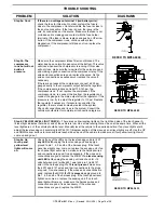
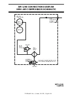
Step 5b. The
compressor
runs but will not
build air
pressure.
Make sure the compressor intake filter is not blocked. The
water trap has a normally open valve at the bottom. This valve
will close whenever the compressor is running. If this valve
will not close, make sure the two wires for the valve are good
and making a good connection at the compressor relay. If the
wires and connections are good, replace the valve. Fix the
wires or connections as necessary or replace the valve if
necessary.
If there are no leaks at the compressor, connect a 200 psi
gauge directly to the compressor output before the regulator.
If the compressor produces at least 130-140 psi, the
compressor is ok. If not, replace the compressor. If the
compressor is ok, re-connect the line from the regulator and
connect the gauge to the main output after the regulator. If the
pressure is low, try to adjust the regulator to 110 psi. Replace
the regulator if necessary. If pressure is good after the
regulator, there is a leak somewhere else in the system.
Check all connections and lines in the system. Consult the
vehicle manufacturer for complete air connection diagrams.
NORMALLY OPEN AIR SOLENOID (1)
12 VOLT RELAY (2)
AIR FILTER
AIR LINE TO SUSPENSION
CHECK VALVE (3)
GRAY FROM
AIR SOLENOID
GROUND
FUSE
15 AMP
FLOW
GROUND TO RELAY MOUNTING BOLT
TO +12 BATTERY
POWER - 6100
REFER TO MP84.6085
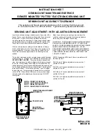
Step 6. YELLOW LEVEL LIGHT CHECK –
There are 4 yellow leveling lights on the right hand side of the touch panel. A
lit level light indicates that side or end of the vehicle is low. One or two level lights can be on at the same time. When all the
level lights are out, the vehicle should be level. Manually level the vehicle to the desired position. If any level lights are lit,
adjust the level sensing unit according to MP44.1511 (diagram section of this manual) so all level lights are off. Use the UP
and DOWN arrow buttons to raise and lower each side and end of the vehicle to make sure all four yellow level lights will
come on and go out.
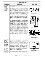
Step 6a. No
touch panel
yellow level
lights will come
on.
Check if any of the LEDs on the level sensing unit are lit.
If
any LED is lit,
unplug the level sensing unit and apply a
ground to pin 1, 4, 5 and 6 of the harness plug. If the touch
panel level lights now come on, replace the sensing unit. If no
touch panel light will come on, make sure the harness wires
and connection are good, fix as necessary. If the wires and
connections are good, replace the MIOM.
If no level sensing
unit LED is lit,
unplug the sensing unit and check for +12
volts between pin 2 (white 6231 wire) and pin 3 (red 6121
wire) in the harness plug.
If +12 is not present,
make sure
the 6231 and 6121 wires and their connections to the plugs
are good. Fix as necessary. If the wires and connections are
good, replace the MIOM.
If +12 is present,
apply ground to
pin 1, 4, 5 and 6 of the harness plug. If the touch panel level
lights now come on, replace the sensing unit. If no touch
panel light will come on, make sure the harness wires and
connection are good, fix as necessary. If the wires and
connections are good, replace the MIOM.
1 2 3
6
5
4
SEE WIRE
LEGEND
BELOW
SEE
ELECTRICAL
CONNECTION
DIAGRAM
FRONT AIR
MANIFOLD
I/O MODULE
MP84.3180
SEE ELECTRICAL CONNECTION
DIAGRAM - HARNESS ROUTING
MOUNTING / ADJUSTMENT
SCREWS (3)
A
B
D
C
YELLOW LEDS
BOTTOM VIEW OF
SENSING UNIT
LED A - FRONT OF VEHICLE
LED B - LEFT SIDE OF VEHICLE (DRIVER SIDE)
LED C - REAR OF VEHICLE
LED D - RIGHT SIDE OF VEHICLE (PASSENGER SIDE)
REFER TO MP84.3433


