


C:\TEMP\ml59101.doc | Revised: 20JUN18 | Page 11 of 39
TROUBLE SHOOTING
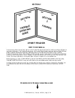
PROBLEM
SOLUTION
DIAGRAMS
6101
6102
CR2
BA
RESET SWITCH (NC)
6100
6101
6101
6101
6100
FUSE
5 AMP
TO +12 BATTERY
87
85
86
30
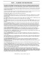
REFER TO MP84.3200
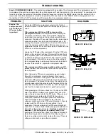
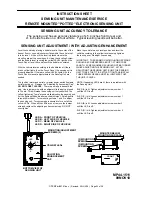
Step 1b. Cont.
The five amp fuse for +12 battery power to the latch in
relay assembly is blown.
Turn the ignition off. Replace the
fuse. If the fuse blows, the problem is on the red 6100 or red
6101 wire between the latch in relay assembly and the fuse. If
the fuse does not blow, unplug the front MIOM. Turn the
ignition key on. If the fuse blows, the issue is on the red 6102
between the relay assembly and the front MIOM. If the fuse
does not blow, turn the ignition off. Unplug the rear MIOM,
both touch panel plugs and the level sensing unit. Leave the
front MIOM unplugged. There should be no continuity
between the red wires for pins B1, C1, D1 of the front MIOM
main connector and any white wires in the main harness or to
any frame ground. Check for continuity and fix as necessary.
If the harness wires are ok, turn the ignition on and plug the
front MIOM back in. If the fuse blows, replace the MIOM. If the
fuse does not blow, plug in the rear MIOM. If the fuse blows,
replace the rear MIOM. If the fuse does not blow, plug in the
5-pin MTA touch panel connector. If the fuse blows, replace
the touch panel. If the fuse does not blow, plug the 6-pin UML
touch panel connector back in. If the fuse blows, there is a
problem with the red 6110 wire in the warning light pigtail.
Repair as necessary. If the fuse does not blow, plug the level
sensing unit back in. If the fuse blows, replace the sensing
unit. If the fuse does not blow, continue with system
diagnostics as needed.
TRUNK
HARNESS
HWH MAIN
HWH MAIN
HARNESS
TRUNK
RESISTOR
TERMINATING
DO NOT CUT
TERMINATING
RESISTOR
DO NOT CUT
TOUCH PANEL
SEE MP84.6195
MASTER
WARNING
LIGHT
7699
6110
LATCH
SYSTEM
LEVEL SENSING UNIT
SEE MP84.3433
A
B
FRONT AIR MANIFOLD
I/O MODULE
SEE MP84.3180
SEE MP84.3190
I/O MODULE
REAR AIR MANIFOLD
HWH COMPUTERIZED LEVELING
WARNING!
UNDERSTAND OPERATOR'S MANUAL BEFORE USING. BLOCK FRAME AND TIRES
CANCEL
M O D E
TRAVEL
LEVEL
MODE
TRAVEL
RAISE
B R A K E
PARK/
SLOPE
EXCESS
NOT IN
DUMP
AIR
SECURELY BEFORE REMOVING TIRES OR CRAWLING UNDER VEHICLE.
REFER TO MP84.3060
WARNING: DO NOT CRAWL UNDER THE VEHICLE UNLESS THE VEHICLE IS SECURELY SUPPORTED AND
CANNOT DROP WHEN AIR IS EXHAUSTED FROM THE SUSPENSION AIR BAGS. MAKE SURE THERE IS AMPLE
ROOM UNDER THE VEHICLE TO AVOID MOVING SUSPENSION PARTS WHEN AIR IS EXHAUSTED OR ADDED TO
THE SUSPENSION AIR BAGS. SERIOUS INJURY OR DEATH CAN OCCUR
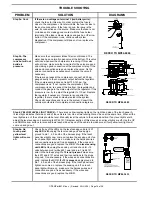
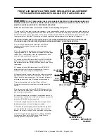
Step 2.
Start the vehicle engine. Make sure there is at least 100 psi in the vehicle air tanks. Push the “TRAVEL MODE”
button. The blue TRAVEL MODE button light should flash a few times. The vehicle should come to ride height. Check that
all the suspension air bags are inflated.
Step 2a. The
blue Travel
Mode button
light does not
flash.
Review Part 1b. Make sure there is good +12 power and
ground to the MIOMs and touch panel and make sure all link
lights are flashing as explained in Step1b. If Step 1b. checks
ok, replace the touch panel.
LEFT FRONT TRAVEL
RIGHT FRONT TRAVEL
REFER TO MP84.3180
OR MP84.3190
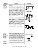
Step 2b. One or
more air bags
are not inflated.
The blue Travel
Mode button
light did flash
If there is a Height Control Valve for each side of the axle, the
issue could be HWH or the Height control valve.
WARNING: MAKE SURE THE FRAME OF THE VEHICLE IS
PROPERLY SUPPORTED BEFORE CRAWLING UNDER
THE VEHICLE. SEVERE INJURY OR DEATH CAN OCCUR.
With the ignition on check that the travel valve LED for the
bag(s) not inflating is lit. There are two travel valves and travel
LEDs on each manifold.
If the travel valve LED is lit,
turn
the “BY-PASS VALVE” T-handle on the side of the manifold
counterclockwise several turns. If the bag inflates, the travel
valve for that bag is most likely the issue.
L
EXHAUST
R
I
VALVE
BY-PASS
[ HCV ]
BAG
AXLE AIR IN
VALVE
BY-PASS
REFER TO MP84.3181


