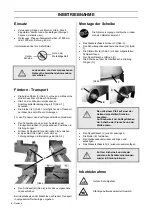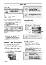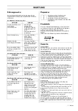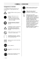
START-UP
Before starting the machine, remove any
wrenches or setting tools.
Keep the safety guard in place for all work.
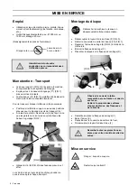
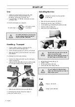
The machine is delivered with an uninstalled head
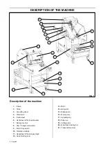
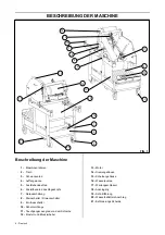
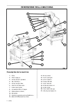
advancement wheel (6) [FIG.1], packed in the accessory
box. Install this wheel on its shaft [FIG.4].
[FIG.4]
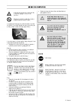
For start-up and after transport, the machine must be
unbridled:
•
Loosen screws (A) until casters are in contact with
the guide bars [FIG.2]
Next,
•
Fill water tank (4) [FIG.1]. (Water pump starts
automatically with motor).
•
Place the material on table (2) according to desired
cut, using cutting guide (18) and rulers [FIG.1].
•
Start
motor:
For heat engine machines:
Æ
Start motor according to manufacturer’s instruction manual.
Æ
Allow motor to warm up.
For electric motor machines:
Æ
Start machine by pressing the “I” button
of the contactor or by turning the contactor
(9) to the “I” position. Turn switch (8) to “Y”
position then to
. [FIG.1]
Next,
•
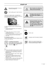
Loosen control handle (12) and turn wheel (11) [FIG.1].
•
Lower saw to desired cutting depth as indicated on
graduated scale. Come down slowly so as to avoid
stalling the motor.
•
When the desired depth has been reached, retighten
the control handle (12).
•
Gently move the cutting head forward using the
wheel (6) [FIG.1]. Advance slowly so as to avoid
stalling the motor.
•
Once the cut has been made, use wheel (6).to gently
back the head up to its maximum rear position.
•
Stop motor (see details in next section)
Before handling the cut material in
any way, stop the motor and wait for
the disc to come to a full stop.
Sound level at the workstation may
exceed 85db (A) and therefore
personal protection equipment must
be worn.
Heat engine machines may not be
operated in a confined space unless
there is sufficient ventilation.
The exhaust gasses contain carbon
monoxide. Exposure to this toxic gas
can cause loss of consciousness
and death.
Stop
Stop the motor
Heat engine: switch off at machine control panel
Electric motor: press red emergency stop
button (7) or turn contactor (9) to position “O”.
Then turn switch (8) to position Y [FIG.1].
9 - English


