INLET SYSTEM
9
18
502 53 07-26
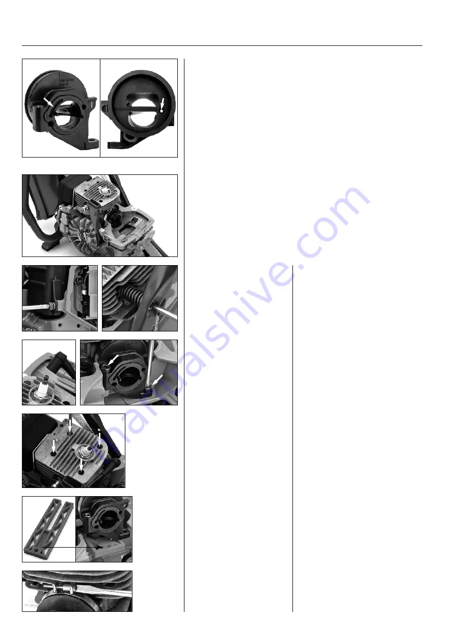
Inlet manifold
The inlet manifold joins the carburettor and cylinder. The inlet manifold
insulates the carburettor from cylinder heat and also provides the carburettor
with vibration damping.
The inlet manifold has separate ducts for the fuel-air mixture and clean air.
The impulse channel (A) leads pressure variations from the crankcase to the
carburettor's pump diaphragm.
It is extremely important that the inlet manifold seals perfectly against the
cylinder and carburettor and that the partition wall in the inlet duct is fitted
correctly in order for the engine to work correctly.
1. Dismantle the muffler's screw on the
crankcase.
2. Dismantle the vibration dampening
on the cylinder.
1. Dismantle the muffler's screw
on the crankcase.
2. Dismantle the vibration
dampening on the cylinder.
3. Lift off the ignition lead.
4. Dismantle the screws on the crankcase.
5. Dismantle the four screws on the base
of the cylinder and lift up the cylinder
slightly. At the same time turn the fly -
wheel to the piston's upper turning point
to keep the piston rings in the cylinder.
5. Dismantle the four screws on
the base of the cylinder and lift
up the cylinder slightly.
3. Lift off the ignition lead.
4. Dismantle the screws on the
crankcase.
1
2
3
4
5
Dismantling
Dismantle the entire air filter unit, cylinder cover, starter and air duct by the
flywheel.
Carefully clean the cylinder fins and the area around the carburettor with
compressed air first. Dismantle the carburettor, see page 6.
The cylinder must be lifted slightly to replace the inlet manifold between
the carburettor and cylinder.
A
A
6
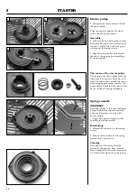
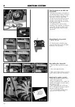
6. Use the support plate in the tool kit
502 50 70-01 to facilitate the work. Place
this between the cylinder and crankcase
to provide support for the cylinder.
6. Place the support plate under
the cylinder.
7. Unscrew the clamp to the outer part of
the screw. Now pry the rubber collar off
of the cylinder.
7. Expand the clamp. Pry the
rubber collar off of the cylinder.
7


