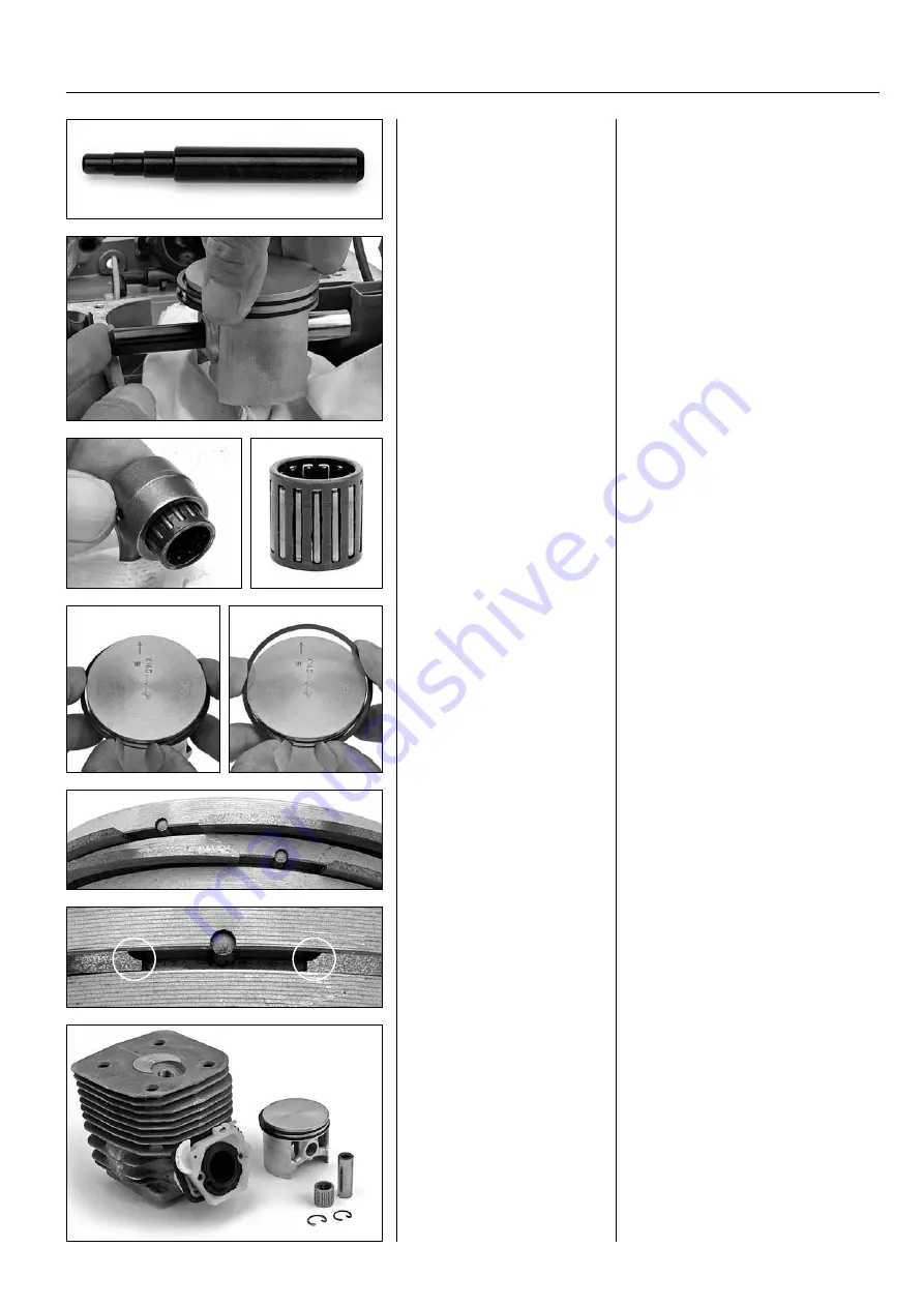
Gudgeon pin punch
Used to dismantle and assemble
the gudgeon pin.
Gudgeon pin punch 505 38 17-05
The gudgeon pin punch is used to press
out the gudgeon pin. It is also used for
assembly.
Dismantle the gudgeon pin
Push out the gudgeon pin in any direc-
tion. Can usually be done by hand. If it
is tight, it can be knocked out with a
small hammer and gentle force. Use a
wooden block or a large plastic hammer
as a counterhold on the opposite side.
Dismantle the gudgeon pin
Push out the gudgeon pin by
hand. If it is tight, it can be
knocked out with a small ham -
mer and gentle force. Use a
counterhold.
Dismantle the needle bearing
Press the needle bearing out of
connecting rod.
Dismantle the needle
bearing
CYLINDER/PISTON
13
32
Piston rings
The piston rings are removed without
tools using the following method:
1. Slide the piston ring towards you so
you can grip the ends. Expand the ring
carefully.
2. Move the piston ring away from you
so that it can be lifted out of the slot at
the rear edge.
Assemble in reverse order.
Piston rings
Remove the piston rings.
505 38 17-05
1
2
Important when assembling
The piston ring groove has a guide pin
that prevents the piston rings from rota-
ting. Fit so that the open part of the
piston ring aligns with the guide pin.
Turn the piston ring with the bevelled
edge towards the guide pin.
Important when assemb-
ling
Fit the open part of the piston
ring so it aligns with the guide
pin.
Turn the piston ring with the
bevelled edge towards the guide
pin.
Examine the components
Investigate the cause of the impaired
compression or failure. With normal
wear, due to many hours of use, com -
ponents are measured (page 33) and
replaced if necessary.
Machines with a few hours of use
should be examined carefully to identify
the cause of the abnormal wear, which is
described later in this chapter.
Examine the components
Investigate the cause of the im -
paired compression or failure.
Machines with a few hours of
use should be examined care -
fully to identify the cause of the
abnormal wear.


