background image

3

Stationary Single Stage Vertical Air Compressors

Introduction

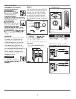
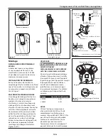
Refer to Figure 1 .

InSTAllInG A ShUT-OFF VAlVe

A shut-off valve should be installed 
on the discharge port of the tank to 
control the air flow out of the tank . The 
valve should be located between the 
tank and the piping system .

pressure switch -

 Auto/Off Switch - In 

the "auto" position, the compressor 
shuts off automatically when tank 
pressure reaches the maximum preset 
pressure . After air is used from the tank 
and drops to a preset low level, the 
pressure switch automatically turns the 
motor back on . In the "off" position, 
the compressor will not operate . This 
switch should be in the "off" position 
when connecting or disconnecting the 
power cord from the electrical outlet .
When the pressure switch turns the 
motor off you will hear air leaking out 
of the pressure switch unloader valve 
for a short time . This releases the air 
pressure from the discharge tube and 
allows the compressor to restart easier .
For units without a manual switch, 
whenever the procedures call for 
turning the switch to the OFF position, 
use the switch at the disconnect instead .

Regulator -

 The regulator controls the 

amount of air pressure released at the 
hose outlet (Sold separately) .

ASMe Safety Valve -

 This valve 

automatically releases air if the tank 
pressure exceeds the preset maximum .

Discharge tube -

 This tube carries 

compressed air from the pump to the 
check valve . This tube becomes very hot 
during use . To avoid the risk of severe 
burns, never touch the discharge tube .

Check valve -

 One-way valve that 

allows air to enter the tank, but 
prevents air in the tank from flowing 
back into the compressor pump .

Belt Guard -

 Covers the belt, motor 

pulley and flywheel .

Tank Drain Valve -

 This valve is located 

on the bottom of the tank . Use this 
valve to drain moisture from the tank 
daily to reduce the risk of corrosion .

MOUnTInG


Never use the wood  

  shipping skids for 

mounting the compressor.

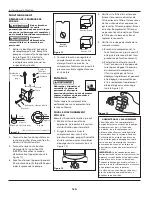
FLOOR MOUNTING (ALL UNITS)

The compressor feet 

MUST

 be bolted to 

a flat, even, concrete floor or separate 
concrete foundation . Vibration isolators 

must be

 used between the tank leg 

and the floor (Part number MP346100AJ 
available separately) . Do not draw 
bolts tight . Allow the pads to absorb 
vibrations . A flexible coupling should be 
installed between the tank and service 
piping .


This compressor is   

  extremely top heavy. 

The unit must be bolted to the floor 
with isolation pads before operating to 
prevent equipment damage, injury or 
death.
 

Never install a shut-   

  off valve between 

the compressor pump and the tank. 
Personal injury and/or equipment 
damage may occur.

pIpInG


Never use plastic   

  (PVC) pipe for 

compressed air. Serious injury or death 
could result.

Any tube, pipe, or hose used must have 
a pressure rating higher then 150 psi . 
Minimum recommended pipe size:
 - up to 50 feet long use 1/2 inch 
 - greater than 50 feet long use 3/4 inch
Larger diameter pipe is always better .

Installation


Disconnect, tag and lock out 
power source, then release 
all pressure from the system 
before attempting to install, service, 
relocate or perform any maintenance.

lOCATIOn


This compressor is  

  not intended for 

outdoor installation.

It is extremely important to install the 
compressor in a clean, well ventilated 
area where the surrounding air 
temperature will not be more than 
100°F .
Provide a minimum clearance of 
18 inches between the compressor 
flywheel or fan to the wall and ensure 
clear access to the drain valve to 
facilitate condensate drainage .
Do not locate the compressor air inlet 
near steam, paint spray, sandblast areas 
or any other source of contamination .

Tank Drain Valve

Discharge Tube

Belt Guard

Check

Valve

Safety

Valve

Pressure

Switch

Tank 

Outlet / 

Discharge 

Port

Tank 

Pressure

Gauge

Figure 1 - 

Some compressors may have a  


different appearance, but they  


have similar parts .

Summary of Contents for VT631402

Page 1: ...th this product carefully Be thoroughly familiar with the controls and the proper use of the equipment Safety Guidelines This manual contains information that is very important to know and understand...

Page 2: ...nt or excessive grease An ASME code safety relief valve with a setting no higher than the maximum allowable working pressure MAWP MUST be installed in the tank for this compressor The ASME safety valv...

Page 3: ...oisture from the tank daily to reduce the risk of corrosion Mounting Never use the wood shipping skids for mounting the compressor FLOOR Mounting all Units The compressor feet must be bolted to a flat...

Page 4: ...rounding screw on the pressure switch A properly sized cord with a ground conductor and plug may also be installed by the user Improperly grounded motors are shock hazards Make sure all the equipment...

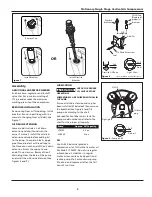
Page 5: ...ation Check for proper Oil level before operating Some models are shipped with oil in the pump Ensure oil drain extension and cap has been installed if included then remove the breather See Figure 8 a...

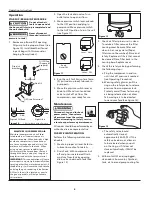
Page 6: ...Disconnect tag and lock out power source then release all pressure from the system before attempting to install service relocate or perform any maintenance All repairs should be performed by an author...

Page 7: ...lel to the straightedge See Figure 14 g If necessary use a gear puller to move the pulley on the motor shaft Tighten setscrew after pulley is positioned h Reattach belt i Reattach belt guard MAINTENAN...

Page 8: ...ve plate 6 Remove the compressor head and valve plate and inspect for carbon deposits or other foreign matter on top of piston Replace head and valve plate using new gasket See Lubrication section for...

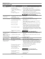
Page 9: ...and the shut off valve is closed 1 Air leaks fittings tubing on compressor or plumbing outside system 1 Check all connections with soap and water solution Tighten or remove and apply sealant to threa...

Page 10: ...or surroundings b Pump or valve failure caused by rain excessive humidity corrosive environments or other contaminants c Cosmetic defects that do not interfere with compressor functionality d Rusted...

Page 11: ...il est n cessaire de suivre les pr cautions suivantes Directives de S curit Ce manuel contient de l information tr s importante qui est fournie pour la S CURIT et pour VITER LES PROBL MES D QUIPEMENT...

Page 12: ...libre d huile de solvants et de graisse excessive Une soupape de s ret ASME avec r glage d au plus la pression de fonctionnement permise maximum PFPM DOIT tre install e dans le r servoir de ce compre...

Page 13: ...ieur Il est tr s important d installer le compresseur dans un endroit propre et bien a r o la temp rature de l air ne d passera pas 38 1 C Une distance minimum de 45 7 cm est requise entre le volant d...

Page 14: ...er des fils permanents de la source d lectricit au manostat avec un fil de terre branch la vis de terre sur le manostat Vous pouvez aussi installer un cordon de taille correcte avec un fil de terre et...

Page 15: ...assurer que le rallonge de vidange d huile et le bouchon soient install s si compris Enlever le reniflard de la r glette jauge Voir Figure 8 et remplir la pompe d huile selon le tableau Se r f rer la...

Page 16: ...onneuse ne pas laver les filtres en papier Rincer et s cher Remplacer les filtres qui ne peuvent pas tre nettoy s Placer le filtre dans la base du carter et replacer le couvercle 4 V rifier la soupape...

Page 17: ...D placer le moteur dans la bonne direction Resserrer les quatre attaches retenant le moteur la plaque de base La courroie doit tre bien align e lors de l ajustement 7 Changer l huile a Permettre que l...

Page 18: ...s axes de piston ou pistons us s au besoin Entretenir le niveau d huile correct et changer l huile plus souvent 6 Piston frappe la plaque de soupape 6 Enlever la t te du compresseur et la plaque de so...

Page 19: ...le s condensateur s 9 Fonctionnement d fectueux du moteur 9 Remplacer le moteur Le r servoir ne conserve pas la pression quand le compresseur est hors circuit et la soupape d arr t est ferm e 1 Fuite...

Page 20: ...ou autres polluants c Les d fauts de forme qui n ont pas d effet sur le fonctionnement du compresseur d Les r servoirs rouill s y compris mais sans s y limiter la rouille caus e par la vidange incorre...

Page 21: ...ras etc intengran un sistema de alta presi n en todo momento deber seguir las siguientes medidas de seguridad Medidas de Seguridad Este manual contiene informaci n que es muy importante que sepa y com...

Page 22: ...a el exterior del compresor limpio sin aceite solvente o exceso de grasa Se DEBE instalar en el tanque de este compresor una v lvula de liberaci n de seguridad codificada por ASME con un valor no mayo...

Page 23: ...ara transportarlo instalacion en el piso Todas las Unidades DEBERA atornillar las patas a una superficie plana y nivelada tal como un piso de concreto o una base de concreto aparte Debe usar almohadil...

Page 24: ...e tambi n instalar un cord n de tama o apropiado con enchufe y cable de tierra Los artefactos el ctricos conectados a tierra incorrectamente constituyen un riesgo de electrocutamiento Cerci rese de qu...

Page 25: ...el aceite y la tapa si se incluyen s quele la varilla al respiradero Vea la Figura 8 y ll nelo de aceite seg n se le indica en la tabla La etiqueta en el tanque de aire especifica el modelo del cabeza...

Page 26: ...o est limpio Para darle servicio al filtro deber destaparlo Desconecte el filtro y l mpielo con agua caliente enjabonada Los filtros de papel no se pueden lavar Sac dalo y d jelo secar Reemplace los f...

Page 27: ...r en la direcci n adecuada Apriete los cuatro sujetadores que sostienen el motor a la placa de la base Despu s de hacer los ajustes debe alinear la banda e Para alinear la banda coloque un objeto rect...

Page 28: ...olo del compresor e inspecci nelos para detectar un desgaste excesivo Reemplace el eje del mbolo s si est excesivamente desgastado o seg n necesario Mantenga el nivel de aceite y cambie el aceite con...

Page 29: ...descarga defectuosa en el interruptor de presi n 7 Cambie la v lvula de descarga 8 Condensador es del motor defectuoso s 8 Cambie el condensador o condensadores 9 Malfuncionamiento del motor 9 Reempl...

Page 30: ...ros contaminantes c Da os de apariencia que no afecten el funcionamiento del compresor d Tanques oxidados incluyendo pero no limitado al xido debido al drenaje inadecuado u agentes corrosivos en el am...

Page 31: ...31 Notes Notas...
Page 32: ...32 Operating Instructions Instructions d utilisation Manual de Instrucciones de Operaci n Notes Notas...

Reviews: