Hunter AutoComp Elite Operation Instruction Manual Download Page 31

1

DIGI-CAL OPERATIONS 

Calibration

1.Select Calibrate Digi-Cal from Menu.                                                                     
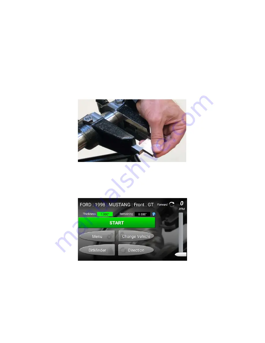
2.Separate the tool holders so the gage block can easily pass between the cutting bits. Then lock 

one tool holder in place. Place the calibration block between the cutting bits. Move the cutting bits 

together  until they both barely touch the calibration block. Press “OK” to continue.                                                                             

Figure 1:   

3. Calibration is complete. Push OK. 

On Car Operation

1. Begin by selecting the appropriate vehicle from “Change Vehicle”. 

Figure 2:                                                                          

2. Select a vehicle manufacturer.
3. Select year.
4. Select make of vehicle.
5. Select front or rear.

Summary of Contents for AutoComp Elite

Page 1: ...Form LM07298 00 08 20 Supersedes 7298 T 10 17 AutoComp Elite On Car Disc Brake Lathe with ACT Copyright 2016 2020 Hunter Engineering Company Operation Instruction...

Page 2: ...Report Technicians Trained Please Print Technician 1 Technician 2 Technician 3 Technician 4 Please have trained technicians initial each training item Brake Lathe Training Task Tech 1 Tech 2 Tech 3 Te...

Page 3: ...elections 7 Lathe Controls 7 Select vehicle 7 Main Screen Features 7 BitMinder 7 Change Vehicle 7 Direction 7 Menu 7 2 Operation Information 9 2 1 Workpiece Rotor Preparation 9 2 2 Twin Cutter Insert...

Page 4: ...9 Flange Plates 19 3 2 Replacing Cutting Inserts 20 Removal 20 Installation 20 3 3 Cleaning and Lubrication 20 Cleaning the Machine 20 Lubrication 20 Care and Maintenance of the Compensation Adaptor 2...

Page 5: ...ion about equipment procedures and maintenance The owner of the lathe is solely responsible for arranging technical training Only qualified Hunter trained techni cians should operate the lathe Maintai...

Page 6: ...d be kept a safe distance from the work area To reduce the risk of fire do not operate the equipment near open containers of any flammable liquids such as gasoline or diesel fuel Do not let cord hang...

Page 7: ...ength 10 gauge wire 50 feet is maximum extension cord length Power Source Grounding Instructions In case of a malfunction or breakdown grounding pro vides a path of least resistance for electric curre...

Page 8: ...d Any modification to the receptacle should be done by a certified electrician Export ACE Lathes 220v Power Source Excluding Canada lathes built for export are meant to be connected to a power source...

Page 9: ...control moves the cutting inserts in towards the hub or out to the outer edge of the rotor Feed Engagement Knob The feed engagement knob is the wing nut located on the rotor feed control This knob is...

Page 10: ...usted to accommodate low and high operational ranges The low range of travel is 20 25 in to 36 25 in 514 35 mm 920 75 mm as mea sured from the lathe output shaft centerline to the floor The high range...

Page 11: ...ation Figure 10 Figure 11 Export Screen shot Touch the button labeled with the correct axle of the vehi cle being serviced either front or rear The correct adap tor lug nut torque and other pertinent...

Page 12: ...8 GETTING STARTED...

Page 13: ...eansers or warm soapy water Remove all rust and corrosion from the mounting sur faces of the workpiece and vehicle hub by using emery paper Scotch Brite abrasive or an electric hand drill equipped wit...

Page 14: ...for standard rotation allowing for a maximum rotor pad surface width of 3 00 in 76 2 mm This setup should only be used on rotors that are thicker than 1 625 in 41 275 mm at the edge Figure 14 Install...

Page 15: ...ting inserts 3 Select the proper hub flange adaptor to fit on vehi cle s rotor 4 Verify that all mounting areas are clean 5 Mount the hub flange adaptor to the rotor Secure the hub flange adaptor to t...

Page 16: ...rocedure Preparation 1 Lift the vehicle and properly chock the wheels 2 Perform a thorough brake inspection Also check all suspension steering and front drivetrain compo nents 3 Remove the wheel Disas...

Page 17: ...y that all mounting areas are clean Use a wire brush to remove rust build up if necessary 2 Attach the proper adaptor to the rotor face by using the vehicle s lug nuts Torque the lug nuts to 40 ft lbs...

Page 18: ...e sure the inside twin cutter does not contact any of the brake mechanisms Adjusting the Twin Cutters 1 First loosen the inboard lock and make sure the out board lock is tightened Turn the locks count...

Page 19: ...button Using the Stabilizer Support Rod Use the stabilizer support rod to prevent lathe from mov ing during heavy cuts or high torque load of vehicle drive train Stabilizer support rod may be extende...

Page 20: ...It is recom mended to work best for the majority of rotors how ever the insert holders may be reversed if necessary to machine larger width rotors 3 Install the micro round inserts using the small tor...

Page 21: ...epth of adjustment knob Make sure the insertholder is all the way in on the rotor face thereby cutting the full surface of the rotor Machine the rotor using normal operation procedures 2 5 Digical Ope...

Page 22: ...d below rotor thickness discard rotor Figure 44 9 Push START when ready to cut 10 Repeat process for Rear rotors The values used to determine these warning levels are change able via Setup under Digi...

Page 23: ...surface fin ish Wipe down adaptors and machined surfaces with rust preventative weekly Insert Maintenance and Replacement Micro Round inserts 221 627 2 should be rotated or replaced when rotor surface...

Page 24: ...Lightly oil the top and bottom guide slides periodically Periodically grease the screw of the carriage movement with EP grease The oil in the gearbox can only be checked or filled by removing the lat...

Page 25: ...parts and TCR1 power units All lift and Hunter TCR1 power units are warranted for a period of two 2 years Normal wear items are not covered with the exception of batteries which are covered for a per...

Page 26: ...22 GETTING STARTED...

Page 27: ...t Rotate or replace insert as needed Insert loose in tool holder Insert must be securely fastened to the tool holder Tool holder loose in cutting tool holder bar Tool holder must be securely fastened...

Page 28: ...24 TROUBLESHOOTING...

Page 29: ...experience Fully equipped service bays Classrooms equipped with modern teaching aids The most up to date wheel alignment balancing service and brake equipment on the market today Classes Available Ali...

Page 30: ......

Page 31: ...in place Place the calibration block between the cutting bits Move the cutting bits together untiltheybothbarelytouchthecalibrationblock Press OK tocontinue Figure 1 3 Calibration is complete Push OK...

Page 32: ...ates an acceptable cut yellow warning approaching minimum rotor thickness Red below rotor thickness discard rotor Figure 4 9 Push START when ready to cut 10 Repeat process for Rear rotors i The values...

Page 33: ...warranted for a period of six 6 months ADASLink units carry a one 1 year warranty and remain under warranty as long as a subscription is maintained thereafter DAS3000 units including electronic circui...

Reviews: