Hunter 50
CC
• DC Electric
7.7
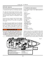
switch. When the water level rises far enough to activate
the float switch, this activates the pump which lowers the
water level down to a point that the float switch stops the
power. Fig. 7.10 shows you the typical wiring.
For more information about your bilge pump system, see
Sanitary Systems.
Battery Switch Panel
Main Distribution Panel
BATTERY TEST
PORT
STBD
DC DISTRIBUTION PANEL
12 VOLT D.C.
24V DC
12V DC
DC AMPS
START-STOP/PRIME
STATUS
Typical Bilge Pump Wiring Diagram
7.2.11 Ventilation
Ventilation is a very important issue with your boat, with
the potential for Carbon Monoxide buildup (See Boating
Safety Section), along with the simple comfort of fresh
air or air conditioning, ventilation is a standard that is a
necessity.
On your boat, there are essentially three types of ventila-
tion, the air conditioning system (AC system), the blower,
and the Bomar hatches, which supply you with fresh
air when opened. Since the air conditioning system is
AC powered (see AC Electric Section) and the hatches
require no power, we will detail the blower (or fans), and
their function, here.
For blower location, consult your Mechanical Arrangement
illustration in the Boating Safety Section, or the Ventilation
illustration in the same section.
WARNING
!
!
Fuel fumes in the engine compartment can explode.
Before working on electrical wiring, ventilate
engine room and disconnect battery cables to
prevent sparks.
The engine room blower is an exhaust fan which will
remove any exhaust fumes from the engine room, as well
as, removing heated air.
7.2.12 Fire Extinguishing Systems
In the engine room, there is a fire extinguishing bottle
installed. This system is DC powered with the relay, or
“module”, and the alarm at the helm station.
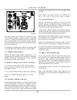
When a fire is detected on your boat, the alarm will sound
and set off the Halon bottle. This relay will shut down the
engines, the blowers, and the generator. To reset the
system, activate the reset switch on the monitor at the
helm. See Fig. 7.9.
Fire Alarm
7.2.13 Shower Sump
The shower sump is part of the Sanitary System and
more information about the Shower Sump can be found
in that section. However, the breaker control for the
Shower Sump can be found on the MDP.
7.2.14 Windlass
Your boat may be equipped with an optional windlass. It
receives its power from the DC electrical system. The
windlass offers you the ability to raise and lower your
anchor. There is also a circuit breaker at the battery
switch. The windlass can be operated from the bow. See
manufacturer’s owner’s manual about the proper and
safe operating procedures. See Fig. 7.12.
Battery Switch
Power
Source
Source
S
Float
at
at
att
F
F
F
F
F
F
F a
a
a
a
o
Switch
Switch
Switch
S
t h
S
t h
h
h
h
h
h
h
t
STATUS
STATUS
Pump
m
m
tc
Fig.7.8
Summary of Contents for 50CC
Page 1: ...Operator s Operator s Manual Manual Hunter 5 Hunter 50 0cc cc ...
Page 2: ......
Page 9: ...Introduction Introduction Hunter 50cc Hunter 50cc Chapter 1 Chapter 1 ...
Page 14: ...Hunter 50cc Introduction 1 6 Notes ...
Page 15: ...Documents Documents Forms Forms Hunter 50cc Hunter 50cc Chapter 2 Chapter 2 ...
Page 26: ...Hunter 50CC Documents and Forms Maintenance Log Date Maintenance Performed Hourmeter 2 12 ...
Page 27: ...Hunter 50CC Documents and Forms 2 13 Date Maintenance Performed Hourmeter Maintenance Log ...
Page 33: ...Hunter 50CC Documents and Forms 2 19 Spare Parts List ...
Page 34: ...Hunter 50CC Documents and Forms Dates of practice drills and onboard safety inspections 2 20 ...
Page 36: ...Hunter 50CC Documents and Forms Notes 2 22 ...
Page 37: ...DC 071609 Limited Limited Warranty Warranty Chapter 3 Chapter 3 ...
Page 38: ...This Page Intentionally Left Blank Hunter Limited Warranty 3 2 ...
Page 47: ...Boating Safety Boating Safety Hunter 50cc Hunter 50cc Chapter 4 Chapter 4 ...
Page 66: ...Hunter 50CC Boating Safety 4 20 Notes ...
Page 67: ...Fuel Systems Fuel Systems Hunter 50cc Hunter 50cc Chapter 5 Chapter 5 ...
Page 73: ...Fig 5 7 A Quick Fuel Filter Reference Hunter 50CC Fuel Systems 5 7 ...
Page 81: ...Underwater Underwater Gear Gear Hunter 50cc Hunter 50cc Chapter 6 Chapter 6 ...
Page 92: ...Hunter 50CC Underwater Gear 6 12 Notes ...
Page 93: ...DC Electrical DC Electrical Systems Systems Hunter 50cc Hunter 50cc Chapter 7 Chapter 7 ...
Page 104: ...NAV LIGHT BREAKER DECK LIGHT BEAKER D Hunter 50CC DC Electric 7 12 ...
Page 105: ...AC Electric AC Electric Systems Systems Hunter 50cc Hunter 50cc Chapter 8 Chapter 8 ...
Page 114: ...Hunter 50cc AC Electric Systems 8 10 Notes ...
Page 115: ...Water Systems Water Systems Hunter 50cc Hunter 50cc Chapter 9 Chapter 9 ...
Page 127: ...Waste Waste Systems Systems Hunter 50cc Hunter 50cc Chapter 10 Chapter 10 ...
Page 140: ...Notes Hunter 50CC Waste and Sanitation Systems 10 14 ...
Page 150: ...Hunter 50CC Engines and Transmissions 11 10 Notes ...
Page 151: ...Sails Sails and and Riggings Riggings Hunter 50cc Hunter 50cc Chapter 12 Chapter 12 ...
Page 164: ...12 14 CAMCLEAT 1 2 5 4 11 3 2 12 7 8 9 10 6 50cc DUAL END MAINSHEET PURCHASE ARRANGEMENT ...
Page 175: ...Hunter 50cc Hunter 50cc Getting Getting Underway Underway Chapter 13 Chapter 13 ...
Page 182: ...Hunter 50CC Getting Underway 13 8 Notes ...
Page 183: ...Maintenance Chapter 14 Chapter 14 Hunter 50cc Hunter 50cc ...
Page 195: ...Glossary Glossary Chapter 15 Chapter 15 Hunter 50cc Hunter 50cc ...


