background image

3

532821-2_A

ICE HELIX® SERIES


Installation Guide


2


|

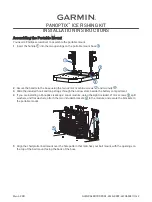
  Installing the Front Battery Cover and Gimbal Bracket

1.  Align the gimbal bracket standoffs to the front openings in the handle. The bracket tab should 

be facing down and toward the back of the shuttle.

NOTE: 

Some models come with multiple gimbal brackets. Make sure to select the gimbal 

bracket that corresponds with your control head.

2.  Secure the gimbal bracket to the shuttle handle using two included #10 - 32 x 1/2" screws. 

Hand-tighten only. See the illustration 

Installing the Gimbal Bracket

3.  Align the front battery cover with the grooves in the front of the shuttle base.

4.  Thread the two tie-down straps on the bottom of the front battery cover through the slots in 

the base. You will attach these to the back battery cover tie-down straps in a later step.

5.  Slide the front battery cover snuggly into the grooves of the shuttle base.

6.  Secure the front battery cover to the handle using the four included #8 – 32 x 3/8" screws and 

#8 flat washers. See the illustration 

Attaching the Front Battery Cover

.

7.  From the back of the shuttle, secure the front battery cover to the bracket by inserting a #8 – 

32 x 3/8" screw and #8 flat washer through the bracket tab and into the battery cover. See the 
illustration 

Attaching the Front Battery Cover

.

3


|

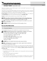
  Installing the Battery and Connecting Power

1.  Turn the shuttle on its side. Thread the two included battery tie-down straps from the bottom 

of the base up through each side of the battery well, using the strap holes. Make sure the soft 
side of the strap faces down.

NOTE:

 There are two battery size options. Use the wider strap holes for the 20 volt battery 

and the narrower strap holes for the 15 volt battery.

2.  Turn the base right side up and pull up gently on the battery tie-down straps to remove the slack.
3.  Move the tie-down straps out of the way so that the battery well is fully accessible.
4.  Place the battery on the foam pad and push the battery into the battery well. Make sure that 

the spade terminals are on the right side of the battery well and that the foam pad fits evenly 
around the battery well edges. See the illustration 

Installing the Battery

.

5.  Slide the positive (red) spade connector from the power backbone onto the positive (red) 

connector adapter on the charging cable (connected to the battery). Slide the negative (black) 
spade connector from the power switch onto the negative (black) connector adapter on the 
charging cable (connected to the battery).


WARNING! 

Do not charge the battery and power the control head or other electronics at the 

same time. 
 

CAUTION! 

Ensure that you connect the correct spade connector to the correct battery 

terminal. Damage to the battery or device, or bodily harm may occur if the device is 

improperly connected to the battery.

6.  Pull the two battery tie-down straps over the top of the battery and connect both ends of each 

strap over the top. Make sure that the straps are pulled tight around the battery, and that the 
straps are not covering the battery LCD viewing window. Manage the power cables by routing 
them under the straps.

7.  Route the control head power cable from the power backbone through the cable pass-through window.

NOTE:

 The power switch includes three SAE cables for auxilliary use. If used, the cables 

connected to the SAE cable can be routed through the side grommets on the back battery 

cover.

Attaching the Front Battery Cover

Installing the Gimbal Bracket

Installing the Battery

foam pad

spade 

terminals

Summary of Contents for ICE HELIX Series

Page 1: ...SK lithium ion battery and battery charger WARNING Misusing the battery may cause a shortened life span or may present a risk of damage to the device and or bodily injury Be sure to follow the safety...

Page 2: ...u re ready to fish ICE HELIX Series Shuttle Assembly Perform the ICE HELIX shuttle assembly tasks in order referring to the step by step procedures When you are finished the control head and the trans...

Page 3: ...r the 20 volt battery and the narrower strap holes for the 15 volt battery 2 Turn the base right side up and pull up gently on the battery tie down straps to remove the slack 3 Move the tie down strap...

Page 4: ...llustration Attaching the Cable Clamp Attaching the Float float transducer transducer cable Attaching the Cable Clamp transducer cable cable clamp acts as a stop for the transducer cable sets depth of...

Page 5: ...so do not force the connector into the wrong port For HELIX 8 9 and 10 models use the following instructions to route the cables to the cable tray 1 Route all cables power transducer accessories Ethe...

Page 6: ...on the cable tray to confirm the installation is secure 11 Remove the cable tray optional Squeeze the sides of the cable tray until it releases Mount the control head 1 Place 1 rubber washer onto eac...

Page 7: ...er well 3 Disconnect Power Unplug the power cable when not in use Optional Fully charge battery after use Maintenance Your Humminbird ICE fish finder is designed to provide years of trouble free opera...

Page 8: ...l interference to radio communications However there is no guarantee that interference will not occur in a particular installation If this equipment does cause harmful interference to radio or televis...

Page 9: ...au lithium ion NORSK et un chargeur de batterie AVERTISSEMENT Une mauvaise utilisation de la batterie peut r duire sa vie ou pr senter un risque de blessures corporelles ou de dommages au dispositif V...

Page 10: ...navette de la s rie ICE HELIX Effectuez les t ches d assemblage de la navette ICE HELIX dans l ordre en vous r f rant aux proc dures tape par tape Une fois l op ration d assemblage termin e la t te de...

Page 11: ...et les trous plus troits pour la batterie de 15 volts 2 Remettez le socle l endroit et tirez sans forcer sur les sangles de la batterie pour liminer le mou 3 D gagez les sangles de fixation du logemen...

Page 12: ...u c ble du transducteur r gle la profondeur du transducteur dans le trou de glace 6 Faites passer le c ble du transducteur par l oeillet avant de la navette ICE et faitesle ressortir par la fen tre de...

Page 13: ...t 10 suivez les instructions suivantes pour acheminer les c bles vers le plateau de c blage 1 Acheminez tous les c bles alimentation transducteur accessoires Ethernet travers la fen tre de passage du...

Page 14: ...e 10 Tirez doucement le plateau de c blage pour v rifier que l illustration est s curis e 11 Retrait du plateau de c blage facultatif Pressez les c t s du plateau de c blage jusqu ce qu il se d tache...

Page 15: ...gement 3 D brancher l alimentation teignez l interrupteur d alimentation Facultatif Rechargez compl tement la batterie apr s utilisation Entretien Votre d tecteur de poissons Humminbird ICE a t con u...

Page 16: ...nuisibles aux communications radio Cependant il n y a aucune garantie que des interf rences ne surviendront pas dans une installationsp cifique Sicet quipementprovoquedesinterf rences nuisibles la r c...

Reviews:

Related manuals for ICE HELIX Series