Waypoints, Routes and Tracks
Waypoints
are stored positions that allow you to mark areas of interest or
navigation points. Your 900 Series™ can store up to 3000 waypoints.
Routes
link two or more waypoints together to create a path for navigation,
and are used in trip planning. You can link individual waypoints together by
using the GOTO key. A route represents your intended navigation and shows
the shortest path from each waypoint to the next. As you travel a route,
staying on the route line is the most efficient way to get to your destination,
although you should always look out for obstacles not shown on the chart.
Your 900 Series™ can store up to 50 routes that can each contain up to 50
waypoints.
Tracks
consist of detailed position history, and are displayed as a
breadcrumb trail of trackpoints. The Current Track shows the position history
since the unit was powered up (maximum of 20,000 trackpoints displayed).
You can clear the Current Track or save it at any time. Your 900 Series™ can
store up to 50 saved tracks, each containing 20,000 trackpoints. The current
track represents your actual path so far.
Waypoints, Routes and Tracks
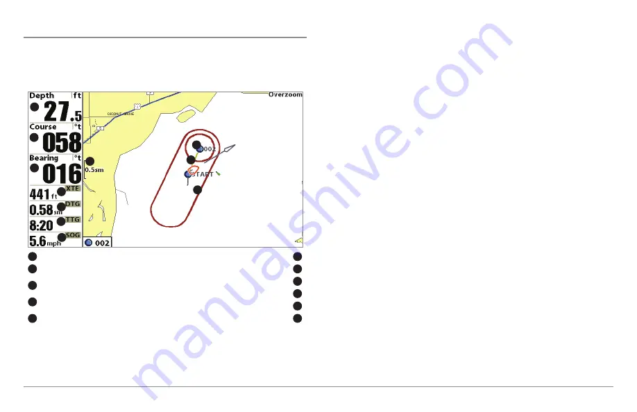
Depth
TTG: Estimate of Trip Time to Destination Waypoint
1
6
Course: Direction that boat is traveling
relative to North Reference
Speed Over Ground: Speed of Boat
2
7
Bearing: Direction to Destination Waypoint
Relative to North Reference
Waypoint
3
8
XTE: Cross Track Error. Distance of Boat
from Route
Route
4
9
DTG: Distance to Go to Waypoint
Off-Course Alarm Limits
5
10
Map Scale
11
1
5
8
4
2
3
7
11
9
10
6
58
Summary of Contents for 997c SI Combo
Page 1: ......
Page 8: ......
Page 147: ...Notes 139...
Page 148: ...Notes 140...
Page 149: ...Notes 141...
Page 150: ...Notes 142...