background image


© 

2008 by Huchez Treuils S.A.S.


Translation of original manual


13

UK 

Reproduction prohibited


VS 1000 kg- VS 1450 kg


Rep. 

N° 

Description 


Rep. 

N° 

Description 

10 

11 

12 

13 

14 

15 

16 

17 

18 

19 

20 

21 

22751 

22752 

22753 

22754 

22755 

22756 

22757 

22758 

22910 

22914 

22915 

22916 

22917 

22918 

22928 

22929 

22942 

22949 

22950 

22951 

22955 

Frame 

Screw 

44-tooth gear 

VS no. 2 rear bearing 

Rear bearing plate 

Cover 

Ratchet 

Lock washer 

Front bearing 

Link pin 

Catch 

Crank head 

Lock button 

Assembled long crank 

Disengaging pin 

Disengaging lever 

Drum 

Drum shaft 

Gear hub 

Plate 

36x47x05 spacer 

22 

23 

24 

25 

26 

27 

28 

29 

30 

31 

32 

33 

34 

35 

36 

37 

38 

39 

40 

41 

22978 

22996 

2760 

2766 

2768 

2773 

2774 

2779 

13505 

13622 

13641 

13646 

13650 

13651 

13659 

13661 

13662 

13664 

13665 

21045 

12x50x3 washer 

Detent spring 

GSM 1214 09 ring 

GSM 4044 14 ring 

GSM 3539 26 ring 

GSM 2225 25 ring 

Cable clamp 

Disengaging spring 

7144-7 ring 

M6 spring nut 

TBHc  screw M6x20 

TBHc  screw M12x20 

TFHc  screw M8x20 

TFHc  screw M8x25 

3.2x18  aluminium rivet 

Thrust roller bearing 8-11-05 

GS washers 8-11-05 

40x1.75 spring retaining ring 

M8 stainless-steel nut 

E12 spring retaining ring 


Summary of Contents for MANIBOX VS 1000

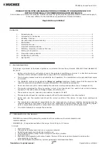
Page 1: ...2008 by Huchez Treuils S A S Hand wormgear winch Hand winch MANIBOX VS Instruction manual _________________________ UK 51 314 09 5...

Page 2: ...he machine in the conditions provided for Never use this winch with a load exceeding the maximum working load specified see p 3 paragraph 2 4 This device is designed for lifting or pulling a load In n...

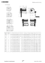
Page 3: ...0 130 103 180 35 56 50 300 1450 B 302 470 290 302 322 167 45 20 4 17 250 340 180 130 103 180 35 56 50 300 1500 B 350 518 330 330 370 200 50 25 4 21 250 340 194 162 105 220 39 5 58 123 50 350 2000 B 35...

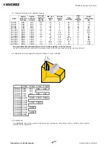
Page 4: ...9 10 11 5 12 13 13 15 8 16 11 11 14 14 14 14 14 14 14 5 14 5 15 15 17 17 11 11 8 8 6 6 5 5 3 3 7 5 7 5 12 12 37 5 37 5 52 52 80 80 140 140 The rope diameter provided above refers to the capacity on th...

Page 5: ...embly and commissioning Please observe the following precautions 4 1 Fixing Fixing screws VS 250 4 screws 10 mm VS 320 4 screws 10 mm VS 500 4 screws 12 mm VS 750 4 screws 12 mm VS 1000 4 screws 16 mm...

Page 6: ...e In the event of an error a safety device is provided to prevent incorrect winding of the rope the operator gets the impression of turning with no load In this case remove the rope and attach it in t...

Page 7: ...2000 2500 3000 or 3500 To engage it again turn the knob until it engages CAUTION Never disengage a loaded winch Before disengaging make sure no load is connected to the rope The rope should not be un...

Page 8: ...risk of overloading due to adherence to the floor suction jamming etc Take warning against the following improper uses or handling operations It is prohibited to Lift loads exceeding the rated load sp...

Page 9: ...to dispose of the device i e to put it out of operation and dismantle it if required 10 Frequently asked questions Problem found Possible causes Solutions The drum does not turn when the handle is tu...

Page 10: ...2008 by Huchez Treuils S A S Translation of original manual 10UK Reproduction prohibited 11 Declaration of confirmity...

Page 11: ...x05 spacer Cover Piles Rear bearing Detent spring Ratchet Lock washer Front bearing Link pin Catch Crank head 18 19 20 21 22 23 24 25 26 27 28 29 30 31 32 33 22917 22933 2760 2763 2766 2772 2777 13505...

Page 12: ...Link pin Catch Crank head Lock button Drum Drum shaft Spacer hub Plate Disengaging pin Disengaging lever 20 21 22 23 24 25 26 27 28 29 30 31 32 33 34 35 36 37 22932 22933 2760 2765 2766 2772 2775 2779...

Page 13: ...ock button Assembled long crank Disengaging pin Disengaging lever Drum Drum shaft Gear hub Plate 36x47x05 spacer 22 23 24 25 26 27 28 29 30 31 32 33 34 35 36 37 38 39 40 41 22978 22996 2760 2766 2768...

Page 14: ...oth gear Release button Front bearing Ratchet pin Ratchet Crank head Tightening knob Assembled long crank 25 26 27 28 29 30 31 32 33 34 35 36 37 38 39 40 41 42 43 44 45 46 47 48 22978 22996 2749 2760...

Page 15: ...shaft Ratchet Handle head Locking button Assembled long handle GR VS 2000 drum shaft 25 26 27 28 29 30 31 32 33 34 35 36 37 38 39 40 41 42 43 44 45 46 47 48 22979 22996 2749 2760 2766 2770 2773 2778 2...

Page 16: ...ngaging boss Disengaging pin Handle unit Disengaging button Front bearing Ratchet shaft Ratchet Handle head 29 30 31 32 33 34 35 36 37 38 39 40 41 42 43 44 45 46 47 48 49 50 51 52 53 54 55 56 22917 22...

Reviews: