©
2008 by Huchez Treuils S.A.S.
Translation of original manual
5
UK
Reproduction prohibited
2.6. Operation
When operating the crank, depending on the direction of rotation, the load goes up or down. When no
more force is exerted on the crank, the brake comes into action and maintains the load in position.
There must be sufficient force on the machine
Table of minimum forces: load
VS 250
VS 500
VS 1000
VS 1500
VS 2000
VS 3000
VS320
VS 750
VS 1450
VS 2000
VS 2500
VS 3500
10 kg
20 kg
40 kg
60 kg
60 kg
100 kg
3 - Handling - Storage
Above 1,000 kg, to handle and position a winch, place a sling around the drum. This causes the device to
tilt, allowing it to be easily and safely handled.
It is advisable to store this equipment to protect it from bad weather.
4 – Use, assembly and commissioning
Please observe the following precautions:
4.1. Fixing
Fixing screws
VS 250
4 screws Ø10 mm
VS 320
4 screws Ø10 mm
VS 500
4 screws Ø 12 mm
VS 750
4 screws Ø 12 mm
VS 1000
4 screws Ø 16 mm
VS 1450
4 screws Ø 16 mm
VS 1500
4 screws Ø 20 mm
VS 2000
4 screws Ø 20 mm
VS 2000
4 screws Ø 20 mm
VS 2500
4 screws Ø 20 mm
VS 3000
4 screws Ø 24 mm
VS 3500
4 screws Ø 24 mm
All these screws must be at least 6.8 class.
Calculate and check that the fixing supports have enough strength to easily withstand the loads to be lifted
or pulled.
4.2. Rope
Models
Ø
(mm)
Max. capacity
(m)
Number
of layers
VS 250
VS 320
VS 500
VS 750
VS 1000
VS 1450
VS 1500
VS 2000
VS 2000
VS 2500
VS 3000
VS 3500
5
6
7
7
9
10
11.5
12
13
13
15.8
16
15
6
18
3
30
5
23
6
17
6
18.5
7.5
4
2
4
1
4
1
3
1
2
1
2
1
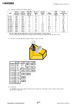
4.3. Installing the rope:
Strictly observe the rope winding direction. To lift the load, turn the crank clockwise: a click will be heard.
To lower the load, turn the crank in the opposite direction.


