UPS5000-S-880 kVA
User Manual (CMI)
3 Installation
Issue 02 (2020-01-10)
Copyright © Huawei Technologies Co., Ltd.
69
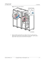
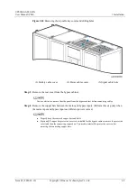
Figure 3-24
Removing the top cable tray covers and drilling holes
(1) Battery cable cover
(2) Power cable covers
(3) Signal cable hole
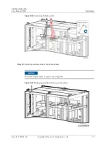
Step 3
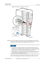
Remove the rear cover from the bypass cabinet.
You are advised to remove the side panel from the bypass cabinet before connecting cables.
Step 4
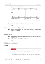
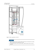
Remove the copper bars between the mains and bypass inputs. (Perform this step only when
the mains input and bypass input use different power sources.)
Properly keep the removed copper bars and bolts.
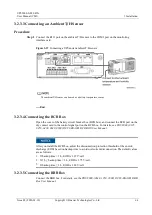
(Optional) If copper bar protective covers are installed for the bypass cabinet, remove the protective
covers and then the connecting copper bars. You need to reinstall the protective covers after
removing the connecting copper bars.


