2.
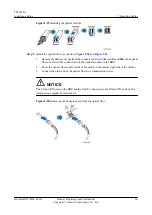
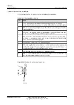
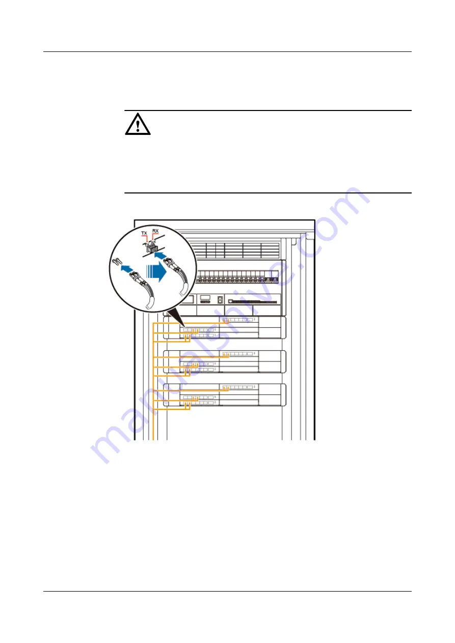
Insert the DLC connectors labeled 2A and 2B at one end of the CPRI optical fibers into the
optical module in the LBBP, and then insert the DLC connectors labeled 1A and 1B at the
other end into the optical module in the RF module.
NOTICE
l
When a CPRI optical fiber connects a BBU and an RRU, the breakout cables on the
BBU side and on the RRU side are 0.34 m and 0.03 m, respectively.
l
If an LC-LC optical fiber is used, the
TX
and
RX
ports on the BBU must be connected
to the
TX
and
RX
ports on the RF module, respectively.
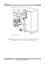
Figure 9-24
Installing CPRI optical fibers
Step 3
Lay out the cables according to the instructions in
and
Step 4
Attach labels to the installed cables by referring to Attaching an L-Shaped Label.
----End
TP48200A
Installation Guide
9 Installing Cables
Issue Draft B (2014-01-20)
Huawei Proprietary and Confidential
Copyright © Huawei Technologies Co., Ltd.
54


