background image

Procedure

Step 1

Prepare the BBU equipotential cable.

1.

Cut the power cable to the required length based on the actual cable route.

2.

Install an OT terminal to both ends of the cable by referring to Assembling the OT Terminal
and the Power Cable.

Step 2

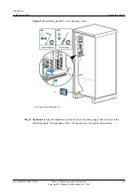
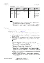
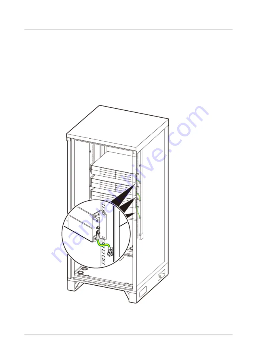
Install the equipotential cable between the BBU and TP48200A, as shown in the following
figure.

Figure 9-13

 Installing BBU Equipotential Cables


Step 3

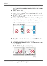
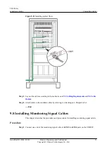
Route the cable by referring to Cabling Requirements. Then use cable ties to bind the cable.

TP48200A
Installation Guide

9 Installing Cables

Issue Draft B (2014-01-20)

Huawei Proprietary and Confidential

Copyright © Huawei Technologies Co., Ltd.

43

Summary of Contents for TP48200A

Page 1: ...TP48200A V100R008C01 Installation Guide Issue Draft B Date 2014 01 20 HUAWEI TECHNOLOGIES CO LTD ...

Page 2: ...e within the purchase scope or the usage scope Unless otherwise specified in the contract all statements information and recommendations in this document are provided AS IS without warranties guarantees or representations of any kind either express or implied The information in this document is subject to change without notice Every effort has been made in the preparation of this document to ensur...

Page 3: ...B V100R006C01 Intended Audience This document is intended for l BTS installation personnel Organization 1 Change History This chapter describes the changes in different document versions 2 Preparing for Installation This section describes the tools and meters that need to be available before the installation It also describes the skills and qualifications that the installation engineers must posse...

Page 4: ...ection describes the procedure for installing components of the TP48200A 9 Installing Cables This section describes how to install cables for the cabinet and other mandatory components 10 Installation Checklist After the cabinets and devices are installed you need to check the installation items installation environment and cable related items 11 Powering On a Base Station This section describes h...

Page 5: ...ions that may be found in this document are defined as follows Convention Description Times New Roman Normal paragraphs are in Times New Roman Boldface Names of files directories folders and users are in boldface For example log in as user root Italic Book titles are in italics Courier New Examples of information displayed on the screen are in Courier New Command Conventions The command convention...

Page 6: ... are in boldface and separated by the signs For example choose File Create Folder Keyboard Operations The keyboard operations that may be found in this document are defined as follows Format Description Key Press the key For example press Enter and press Tab Key 1 Key 2 Press the keys concurrently For example pressing Ctrl Alt A means the three keys should be pressed concurrently Key 1 Key 2 Press...

Page 7: ...sly and quickly without moving the pointer Drag Press and hold the primary mouse button and move the pointer to a certain position TP48200A Installation Guide About This Document Issue Draft B 2014 01 20 Huawei Proprietary and Confidential Copyright Huawei Technologies Co Ltd vi ...

Page 8: ...nstalling Components 22 8 1 Installing a Rectifier 23 8 2 Installing Storage Batteries 23 8 3 Installing a BBU 27 9 Installing Cables 30 9 1 Cabling Requirements 31 9 2 Cable Outlets 37 9 3 Installing the AC Input Power Cable 39 9 4 Installing BBU Equipotential Cables 42 9 5 Installing BBU Power Cables 44 9 6 Installing RRU Power Cables 45 9 7 Installing FE GE Optical Fibers 48 9 8 Installing Moni...

Page 9: ...11 Powering On a Base Station 58 12 Follow up Operations 62 TP48200A Installation Guide Contents Issue Draft B 2014 01 20 Huawei Proprietary and Confidential Copyright Huawei Technologies Co Ltd viii ...

Page 10: ...mpared with draft A 2013 12 30 this issue includes the following changes Topic Description 9 6 Installing RRU Power Cables Modified the installation procedure No information in draft A 2013 12 30 is deleted from this issue Draft A 2013 12 30 This is draft A TP48200A Installation Guide 1 Change History Issue Draft B 2014 01 20 Huawei Proprietary and Confidential Copyright Huawei Technologies Co Ltd...

Page 11: ...ned before the installation 2 2 Tools and Instruments This section lists the tools and instruments that must be obtained before installation 2 3 Skills and Requirements for Onsite Personnel Onsite personnel must be qualified and trained Before performing any operation onsite personnel must be familiar with correct operation methods and safety precautions TP48200A Installation Guide 2 Preparing for...

Page 12: ...uments This section lists the tools and instruments that must be obtained before installation Marker Phillips screwdriver M3 to M6 Flat head screwdriver M3 to M6 Diagonal pliers 32 mm 1 26 in combination wrench Socket wrench Torque wrench Power cable crimping tool RJ45 crimping tool Cable cutter Rubber mallet Soldering iron Wire stripper Hammer drill Φ16 Heat gun Level TP48200A Installation Guide ...

Page 13: ...ods and safety precautions Before the installation pay attention to the following items l The customer s technical engineers must be trained by Huawei and be familiar with the proper installation and operation methods l The number of onsite personnel depends on the engineering schedule and installation environment Generally only three to five onsite personnel are necessary TP48200A Installation Gu...

Page 14: ...ets 3 1 TP48200A Configurations This section describes the hardware configurations in a TP48200A cabinet 3 2 Space Requirements This section describes the space required for maintaining the TP48200A cabinet and routing cables TP48200A Installation Guide 3 Information to Be Known Before the Installation Issue Draft B 2014 01 20 Huawei Proprietary and Confidential Copyright Huawei Technologies Co Lt...

Page 15: ...ing figure shows the TP48200A interior Figure 3 1 Interior of the TP48200A The following table describes the components in the TP48200A TP48200A Installation Guide 3 Information to Be Known Before the Installation Issue Draft B 2014 01 20 Huawei Proprietary and Confidential Copyright Huawei Technologies Co Ltd 6 ...

Page 16: ...ery switch Mandatory 1 The battery switch is used to manually and temporarily power on batteries 4 BBU Mandatory 3 The BBU processes the baseband signals of the base station 5 AC PDU Mandatory 1 An AC PDU feeds external AC power into the cabinet 6 Storage batteries Mandatory 4 Storage batteries provide DC load power when the input AC power is interrupted and the rectifier stops working TP48200A In...

Page 17: ...or maintaining the TP48200A cabinet and routing cables The space requirements for installing a TP48200A cabinet are as follows l A minimum of 1500 mm clearance in front of the cabinet must be reserved l A minimum of 100 mm clearance behind the cabinet must be reserved l A minimum of 200 mm clearance on the left of the cabinet must be reserved l A minimum of 200 mm clearance on the right of the cab...

Page 18: ...ure 3 2 Space requirements TP48200A Installation Guide 3 Information to Be Known Before the Installation Issue Draft B 2014 01 20 Huawei Proprietary and Confidential Copyright Huawei Technologies Co Ltd 9 ...

Page 19: ...installing components or cables take proper electrostatic discharge ESD protection measures for example wear ESD gloves to prevent electrostatic damage to the boards or electronic components The following flowchart describes the procedure for installing a TP48200A TP48200A Installation Guide 4 Installing Procedure Issue Draft B 2014 01 20 Huawei Proprietary and Confidential Copyright Huawei Techno...

Page 20: ...Figure 4 1 Installing procedure TP48200A Installation Guide 4 Installing Procedure Issue Draft B 2014 01 20 Huawei Proprietary and Confidential Copyright Huawei Technologies Co Ltd 11 ...

Page 21: ...edure Step 1 Check whether the component installation is in compliance with the instructions shown in the following figure and table In addition check whether the cables are securely installed Tighten the screws if necessary TP48200A Installation Guide 5 Checking Installed Components and Cables Issue Draft B 2014 01 20 Huawei Proprietary and Confidential Copyright Huawei Technologies Co Ltd 12 ...

Page 22: ...U 5 UIM02C 6 Rectifier Step 2 Check whether the signal cable connections are in compliance with the instructions shown in the following figure and table In addition check whether the cables are securely installed TP48200A Installation Guide 5 Checking Installed Components and Cables Issue Draft B 2014 01 20 Huawei Proprietary and Confidential Copyright Huawei Technologies Co Ltd 13 ...

Page 23: ... Monitoring signal cable for the temperature sensor Sensor Fan box 2 pin connector TEMP1 port on the UIM02C 2 Monitoring signal cable for the door status sensor Door status sensor 2 pin connector GATE port on the UIM02C TP48200A Installation Guide 5 Checking Installed Components and Cables Issue Draft B 2014 01 20 Huawei Proprietary and Confidential Copyright Huawei Technologies Co Ltd 14 ...

Page 24: ...nitoring signal cable for the battery cabinet Sensor Storage batteries 2 pin connector BTEMP on the UIM02C End TP48200A Installation Guide 5 Checking Installed Components and Cables Issue Draft B 2014 01 20 Huawei Proprietary and Confidential Copyright Huawei Technologies Co Ltd 15 ...

Page 25: ... cover from the cabinet packaging box and find the hole marking off template on the cover interior as shown in the following figure Figure 6 1 Taking the marking off template Step 2 Mark the hole positions based on the marking off template as shown in Figure 6 2 Figure 6 3 shows the cabinet dimensions and mounting holes TP48200A Installation Guide 6 Installing the Cabinet Issue Draft B 2014 01 20 ...

Page 26: ...g holes Step 3 Drill holes at the anchor points and then install expansion bolt assemblies as shown in the following figure TP48200A Installation Guide 6 Installing the Cabinet Issue Draft B 2014 01 20 Huawei Proprietary and Confidential Copyright Huawei Technologies Co Ltd 17 ...

Page 27: ...e not at the proper position drill a hole or holes again 3 Tighten the expansion anchor bolts slightly and place one vertically into each hole 4 Use a rubber mallet to hammer the expansion bolt until it goes into the hole completely 5 Remove the M12x60 bolt spring washer plastic pipe and flat washer in sequence NOTE After removing an expansion bolt discard the plastic pipe Step 4 Secure the cabine...

Page 28: ...bolts slightly 4 Use a torque socket to tighten the expansion bolts with a torque of 40 5 N m to 49 5 N m Figure 6 5 Securing the cabinet End TP48200A Installation Guide 6 Installing the Cabinet Issue Draft B 2014 01 20 Huawei Proprietary and Confidential Copyright Huawei Technologies Co Ltd 19 ...

Page 29: ...l and the Power Cable Step 2 Install a PGND cable as shown in Figure 7 2 1 Connect one end of the PGND cable to the site ground bar 2 Route the other end of the cable out of the cable outlet along the bottom left side of the cabinet and connect the cable to the ground bar for the TP48200A NOTICE When installing a PGND cable ensure that the OT terminals on the PGND cable are oriented correctly and ...

Page 30: ...o the instructions in 9 1 Cabling Requirements and 9 2 Cable Outlets Step 4 Label the installed cables according to the instructions in Attaching a Sign Plate Label End TP48200A Installation Guide 7 Installing a PGND Cable Issue Draft B 2014 01 20 Huawei Proprietary and Confidential Copyright Huawei Technologies Co Ltd 21 ...

Page 31: ...utput 8 2 Installing Storage Batteries If a site requires power backup storage batteries must be installed in a TP48200A 8 3 Installing a BBU This section describes the procedure and precautions for installing a BBU in a TP48200A when a TP48200A is deployed outdoors TP48200A Installation Guide 8 Installing Components Issue Draft B 2014 01 20 Huawei Proprietary and Confidential Copyright Huawei Tec...

Page 32: ...to its slot along the guide rail Step 4 Push the handle upwards Step 5 Push the locking latch towards the right to secure the handle Figure 8 1 Installing a rectifier End 8 2 Installing Storage Batteries If a site requires power backup storage batteries must be installed in a TP48200A Prerequisites l Verify that all batteries are of the same model and batch from the same manufacturer The battery v...

Page 33: ... personal safety Procedure Step 1 Verify that the circuit breaker labeled BAT corresponding to the DC PDU is set to OFF Step 2 Install the batteries from left to right as shown in the following figure Figure 8 2 Installing storage batteries Step 3 Install copper bars for connecting storage batteries NOTE Copper bars between batteries are installed in the same way The following procedure describes ...

Page 34: ...n the following figure Figure 8 4 Installing a copper bar between batteries 3 Reinstall the insulation cover for battery 1 as shown in the following figure TP48200A Installation Guide 8 Installing Components Issue Draft B 2014 01 20 Huawei Proprietary and Confidential Copyright Huawei Technologies Co Ltd 25 ...

Page 35: ...gative battery cable from the left side of the battery compartment and install the cable to the negative battery wiring terminal 3 Take the positive battery cable from the right side of the battery compartment and install the cable to the positive battery wiring terminal 4 Reinstall the insulation covers for battery 1 and battery 4 TP48200A Installation Guide 8 Installing Components Issue Draft B ...

Page 36: ... a BBU in a TP48200A when a TP48200A is deployed outdoors Context A maximum of three BBUs can be installed in a TP48200A The following figure shows the BBU installation positions TP48200A Installation Guide 8 Installing Components Issue Draft B 2014 01 20 Huawei Proprietary and Confidential Copyright Huawei Technologies Co Ltd 27 ...

Page 37: ...rform the following operations 1 Remove the four M4 screws from the mounting ear on each side of the BBU 2 Install the mounting ears reversely and tighten the four M4 screws on each of the mounting ears with a torque of 1 2 N m 10 62 lbf in TP48200A Installation Guide 8 Installing Components Issue Draft B 2014 01 20 Huawei Proprietary and Confidential Copyright Huawei Technologies Co Ltd 28 ...

Page 38: ...P48200A and then tighten four M6x16 screws on the panel with a torque of 2 N m as shown in the following figure Figure 8 9 Installing a BBU End TP48200A Installation Guide 8 Installing Components Issue Draft B 2014 01 20 Huawei Proprietary and Confidential Copyright Huawei Technologies Co Ltd 29 ...

Page 39: ...00A to ensure the equipotential bonding between the BBU and TP48200A 9 5 Installing BBU Power Cables A BBU power cable feeds power into the BBU from the DC power distribution unit PDU 9 6 Installing RRU Power Cables An RRU power cable connects a DC PDU and an RRU and feeds power into the RRU from the DC PDU 9 7 Installing FE GE Optical Fibers This section describes the procedure and precautions fo...

Page 40: ...st be bound together l Different types of cables must be separately laid out and bound with a minimum distance of 30 mm 1 18 in from each other l The cables must be bound tightly and neatly The sheaths of the cables must not be damaged l The cable ties must face the same direction and those at the same horizontal line must be in a straight line l The excess of the indoor cable ties is cut off The ...

Page 41: ...ips to secure cables outdoors For the method of installing a clip see the installation guide delivered with the clip l Arrange cables neatly along the routing direction and use clips to secure the cables l Determine the positions where the clips are installed according to the actual situation For example 7 8 feeders are secured with clips at an interval of 1 5 m to 2 m 4 92 ft to 6 56 ft CPRI fibe...

Page 42: ... 9 2 Cables secured on a cable tray 1 3 hole clip 2 6 hole clip The following figure shows the cables secured on a tower TP48200A Installation Guide 9 Installing Cables Issue Draft B 2014 01 20 Huawei Proprietary and Confidential Copyright Huawei Technologies Co Ltd 33 ...

Page 43: ...lace the cables rather than adding connectors or soldering joints to lengthen the cables l Cables can only be laid out under well planned instructions The cabling activities of fiber optic cables are allowed only when qualified personnel and communication facilities are available l Do not circle and twist cables TP48200A Installation Guide 9 Installing Cables Issue Draft B 2014 01 20 Huawei Propri...

Page 44: ...ch other l Switches or fuses must not be installed on the PGND cables l Other devices must not be used for electrical connections of the PGND cables l All the metal parts in the housing of the equipment must be reliably connected to the ground terminal Cabling of E1 cables l E1 cables must not cross power cables PGND cables or RF cables when laid out If transmission cables are laid out with power ...

Page 45: ... a cabinet or a piece of equipment use binding straps to bind it and then use cable ties to secure the binding straps to the cabinet or equipment Ensure that the fiber optic cables can flexibly move in the cable ties Do not bend the fiber optic cables sharply The following figure shows how to bind the fiber optic cables correctly Figure 9 5 Binding fiber optic cables l When coiling fiber optic cab...

Page 46: ...c cable onto a pole or the rails surrounding the platform Ensure that there is no excessively long distance between the equipment and the position where the cable is secured l Coil the excess of the fiber optic cables near the equipment on the tower before securing the cables on the tower 9 2 Cable Outlets This section describes the cabling direction of the TP48200A over the cable outlets The foll...

Page 47: ...located based on the number of onsite optical fibers l Optical fibers are routed from the left cable outlets by default If the left cable outlets are insufficient the right cable outlets are used l If the top BBU is connected to 24 optical fibers it is recommended that the optical fibers are routed from the right cable outlets l The GPS signal cables and optical fibers are routed from the same cab...

Page 48: ...inal M6 25 mm2 Green and yellow Procedure Step 1 Prepare the AC input power cable for the TP48200A 1 Cut the cable to the length suitable for the actual cable route 2 Prepare a cord end terminal and an OT terminal for one end of the cable For details about how to prepare cord end terminals and OT terminals see Assembling the Cord End Terminal and the Power Cable and Assembling the OT Terminal and ...

Page 49: ... corresponding AC input terminals and circuit breakers and secure them as shown in the following figure Figure 9 10 Installing the 220 V or 380 V AC input power cable 1 AC power distribution box TP48200A Installation Guide 9 Installing Cables Issue Draft B 2014 01 20 Huawei Proprietary and Confidential Copyright Huawei Technologies Co Ltd 40 ...

Page 50: ...re the insulation cover to the short circuiting copper bar as shown in the following figure If single phase 220 V AC input power is supplied skip this step TP48200A Installation Guide 9 Installing Cables Issue Draft B 2014 01 20 Huawei Proprietary and Confidential Copyright Huawei Technologies Co Ltd 41 ...

Page 51: ...equipotential cable connects ground bolts on a BBU and a TP48200A to ensure the equipotential bonding between the BBU and TP48200A Context The following table lists the specifications of a BBU power cable Table 9 3 Specifications of a BBU power cable Cable One End The Other End Connector Connected to Connector Connected to BBU equipotential cable OT terminal M4 6 mm2 BBU ground screw OT terminal M...

Page 52: ...inal and the Power Cable Step 2 Install the equipotential cable between the BBU and TP48200A as shown in the following figure Figure 9 13 Installing BBU Equipotential Cables Step 3 Route the cable by referring to Cabling Requirements Then use cable ties to bind the cable TP48200A Installation Guide 9 Installing Cables Issue Draft B 2014 01 20 Huawei Proprietary and Confidential Copyright Huawei Te...

Page 53: ...ls see Assembling the Cord End Terminal and the Power Cable and Assembling the OT Terminal and the Power Cable Step 2 Connect the 3V3 connector at one end of the BBU power cable to the 48V port on the UPEU in the BBU Then tighten the screws on the connector with a torque of 0 25 N m Step 3 Connect the cord end terminal at one end of the blue core wire to the F13 BLVD circuit breaker for the DC PDU...

Page 54: ... instructions in Attaching a Cable Tying Label End 9 6 Installing RRU Power Cables An RRU power cable connects a DC PDU and an RRU and feeds power into the RRU from the DC PDU Context The following table lists the specifications of RRU power cables TP48200A Installation Guide 9 Installing Cables Issue Draft B 2014 01 20 Huawei Proprietary and Confidential Copyright Huawei Technologies Co Ltd 45 ...

Page 55: ...y contacts with the ground clip Then tighten the M4 screw on the ground clip to 1 2 N m 10 62 lbf in NOTE When installing a ground clip for the RRU power cables comply with the following rules l When one to three RRU power cables are installed put all the RRU power cables on one side of the ground screw as shown by illustration 1 in the following figure l When four or six RRU power cables are inst...

Page 56: ...ION Ensure that the RRU power cable for an RRU added to a running base station must be connected to the RRU first and then to the power equipment The operations in the reverse sequence may cause component damage or personal injury TP48200A Installation Guide 9 Installing Cables Issue Draft B 2014 01 20 Huawei Proprietary and Confidential Copyright Huawei Technologies Co Ltd 47 ...

Page 57: ...rminals as shown in the following figure Figure 9 17 Installing RRU power cables Step 5 Lay out the cables according to the instructions in 9 1 Cabling Requirements and 9 2 Cable Outlets Step 6 Label the installed cables according to the instructions in Attaching a Cable Tying Label End 9 7 Installing FE GE Optical Fibers This section describes the procedure and precautions for installing FE GE op...

Page 58: ...e optical module is black or gray l An optical module to be installed must match the rate of its corresponding port Procedure Step 1 Install an optical module as shown in Figure 9 18 and Figure 9 19 1 Remove the dustproof cap from the corresponding FE GE optical port on the corresponding board in the BBU 2 Remove the dustproof cap from the optical module 3 Lower the puller of the optical module 4 ...

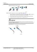
Page 59: ...optical fibers out from the cable outlet on the bottom right side of the cabinet 3 Connect the other end of the optical fibers to a transmission device NOTICE The TX and RX ports on the BBU boards must be connected to the RX and TX ports on the transmission equipment respectively Figure 9 20 Removing the dust proof cap from the optical fiber TP48200A Installation Guide 9 Installing Cables Issue Dr...

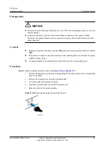
Page 60: ...ching an L Shaped Label End 9 8 Installing Monitoring Signal Cables This chapter describes the procedures and precautions for installing monitoring signal cables Procedure Step 1 Connect one end of the monitoring signal cable to ALM1 to ALM4 ports on the UIM02C TP48200A Installation Guide 9 Installing Cables Issue Draft B 2014 01 20 Huawei Proprietary and Confidential Copyright Huawei Technologies...

Page 61: ... the monitoring signal cable to the EXT_ALM0 or EXT_ALM1 port on the UPEU or UEIU as shown in the following figure Figure 9 22 Installing monitoring signal cables Step 3 Lay out the cables according to the instructions in 9 1 Cabling Requirements and 9 2 Cable Outlets Step 4 Label the installed cables according to the instructions in Attaching an L Shaped Label End 9 9 Installing CPRI Optical Fibe...

Page 62: ...Therefore the optical module must be connected to optical fibers within 20 minutes after being unpacked Procedure Step 1 Install an optical module as shown in the following figure 1 Lower the puller on the optical module 2 Insert the optical module into the CPRI port on an LBBP and then insert the optical module of the same type into the CPRI_W CPRI0 or CPRI0 IR0 port on an RRU NOTE Optical module...

Page 63: ...4 m and 0 03 m respectively l If an LC LC optical fiber is used the TX and RX ports on the BBU must be connected to the TX and RX ports on the RF module respectively Figure 9 24 Installing CPRI optical fibers Step 3 Lay out the cables according to the instructions in 9 1 Cabling Requirements and 9 2 Cable Outlets Step 4 Attach labels to the installed cables by referring to Attaching an L Shaped La...

Page 64: ...nnections are tightened The spring washers and the flat washers are installed in the correct sequence 4 The cabinet is neat and clean 5 The paint on the surface is intact The damaged paint is repaired For details see Applying Touch Up Paint 6 Labels tags and nameplates are correct legible and complete Installation Environment Checklist The following table lists the items to be checked for the inst...

Page 65: ...wires and the terminal handles at the wiring terminals are coated with heat shrink tubing 6 The flat washers and the spring washers are well mounted on all OT terminals 7 The exterior of the storage battery is intact without any scratch dent or crack 8 The shell of the storage battery is clean without any leakage trace 9 The wiring terminal on the storage battery stands properly without any damage...

Page 66: ...city expansion For example the maintenance transfer cable is bound to the outside of the BBU cable claw as shown in the following figure 5 All the labels at both ends of the cables are legible 6 The extra length of the indoor cable ties is cut off and the cut surfaces are smooth without sharp edges The extra length of 3 mm 0 11 in to 5 mm 0 19 in of the outdoor cable ties is reserved when the cabl...

Page 67: ...n conducting the power on check Do not use you hand or damp objects to touch the device with input voltage This might be fatal NOTICE l Power on a TP48200A or BBU within 7 days after unpacking it If you power off a TP48200A or BBU for maintenance restore power to the cabinet or BBU within 48 hours l After you unpack an RRU power on it within 24 hours If you power off the RRU for maintenance restor...

Page 68: ...ower circuit breaker to power on the TP48200A Step 3 Set the circuit breaker on the DC PDU to ON Step 4 Set the power circuit breaker on the UPEU in the BBU to ON and check the power supply to components in the cabinet according to the following table TP48200A Installation Guide 11 Powering On a Base Station Issue Draft B 2014 01 20 Huawei Proprietary and Confidential Copyright Huawei Technologies...

Page 69: ...s are incorrectly connected set all the circuit breakers to OFF and then reconnect the power cables l If the cables are correctly connected replace the power units Failure in the power supply to a board in the BBU Check as follows 1 Remove the board and check whether any pin of the slot on the backplane is bent broken or missing Replace the subrack if necessary 2 Insert the board into the subrack ...

Page 70: ... If the input power is normal replace the component l If the input power is abnormal check whether the power cable for the component is connected securely If the power cable is not securely connected turn off the circuit breaker for the component if there is no circuit breaker for the component remove the connector from the power unit and reconnect the power cable If the power cable is securely co...

Page 71: ...oof mud out of the accessory package to seal the cable outlets that have cables routed out and use plugs or covers to seal the cable outlets that have no cables routed out Step 3 The paint on the surface of the cabinet should be kept intact Therefore any damaged paint must be repaired For details see Applying Touch Up Paint End TP48200A Installation Guide 12 Follow up Operations Issue Draft B 2014...

Reviews: