background image

25

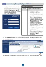
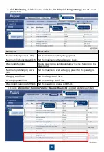
Parameter

Description

Off-grid mode

If this parameter is set to Enable, the ESS switches to the off-grid mode 

when the grid fails.

Backup power SOC

Sets the backup power SOC. In grid-tied mode, the battery does not 

discharge when it is discharged to the backup power SOC. When the grid 

fails, loads are powered in backup mode.

Grid-tied/Off-grid 

mode switching

If this parameter is set to Automatic switching, the system switches to the 

off-grid mode when the grid fails, and switches to the grid-tied mode when 

the grid recovers.

Voltage in 

independent 

operation

Select the voltage in independent operation based on the inverter cable 

connection, 101 V or 202 V.

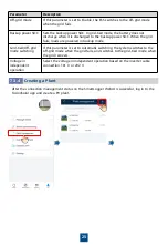
Creating a Plant

7.3.4

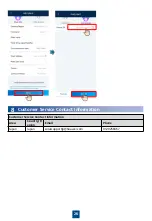
After the connection management status on the SmartLogger WebUI is successful, log in to the 

FusionSolar app and create a PV plant.

Summary of Contents for SUN2000-4.95KTL-JPL1

Page 1: ...HUAWEI TECHNOLOGIES CO LTD SUN2000 4 95KTL JPL1 Quick Guide Issue 03 Part number 31500EET Date 2021 09 10 ...

Page 2: ...otice Every effort has been made in the preparation of this document to ensure accuracy of the contents but all statements information and recommendations in this document do not constitute a warranty of any kind express or implied 2 Before installing the device read the user manual carefully to get familiar with product information and safety precautions 4 Before installing the device check that ...

Page 3: ...3 Installation Space Installation Angle 2 Device Installation Mounting Holes and Dimensions Installation Requirements 2 1 2 ...

Page 4: ...0 2 2 Moving the SUN2000 1 Move the SUN2000 with care to prevent device damage and personal injury 2 When moving the SUN2000 place your hands in the position shown in the following figure to avoid scratches 3 Place a foam pad or cardboard under the SUN2000 to protect the SUN2000 enclosure from damage Installing the SUN2000 2 Place the mounting bracket close to the wall determine the positions for ...

Page 5: ...6 Install the SUN2000 onto the mounting bracket Route the cable through the cable hole in the wall Cable hole for routing cables through a wall 4 ...

Page 6: ...earest ground point It is recommended that silica gel or paint be used around the ground terminal after the PE cable is connected 7 Install the SUN2000 protective cover 5 No Cable Type Conductor Cross Sectional Area Range Cable Outer Diameter 1 PE cable Single core outdoor copper cable 5 5 8 mm2 N A 2 PV input cable Common outdoor PV cable in the industry 3 5 5 5 mm2 5 5 7 3 mm 3 Battery power cab...

Page 7: ...vent rain or snow from entering the maintenance compartment If unavoidable do not open the maintenance compartment door in rainy or snowy days Remove the four screws from the cover Start from the one at the lower left corner and the rest in the counterclockwise sequence 2 Prepare cord end terminals for cables route the cord end terminals into the SUN2000 maintenance compartment through the cable h...

Page 8: ...able holes Installing the AC Output Power Cable 3 4 Ensure that the exposed core wire of the AC output power cable is totally inserted into the cable hole and connected securely Failing to do so may cause device malfunction or damage When connecting the 202 V self supporting output power cable single phase three wire connect it to the transformer first Otherwise the device may be burnt 7 AC Connec...

Page 9: ...te the DC switch and wiring terminals immediately Failing to do so may cause device damage which is not covered under warranty Wait until the night when solar irradiance declines and the PV string current drops to below 0 5 A Then set the DC switch to OFF remove the positive and negative connectors and correct the polarity of the DC input power cables Jacket Bare wire DC input terminals Route the ...

Page 10: ...on Two DC Inputs Connection The DC input terminals are selected as follows If there are two PV strings connect them to the two MPPTs respectively If there are more than two PV strings it is recommended that PV strings with the same number of PV modules connect to the same MPPT If PV strings with different numbers of PV modules connect to the same MPPT energy yield loss will occur 1a 1b 1a 1b 2a 2b...

Page 11: ...e SUN2000 may be damaged Preparing Cables Battery terminal BAT BAT Route the cable terminals into the cable holes Ensure that the cable cannot be pulled out after being crimped 1 PV Cable Preparation Jacket Bare wire Insulation layer 12 mm 50 mm Cord end terminal Recommended CRIMPFOX 10S The PV strings connecting to the same MPPT circuit should use PV modules of the same model and quantity ...

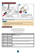
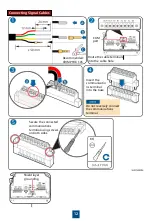
Page 12: ...ling Signal Cables 3 7 When laying out a signal cable separate it from power cables and keep it away from strong interference sources to prevent communication interruption If multiple signal cables need to be connected ensure that the outer diameters of the signal cables are the same 11 Battery Terminal Wiring Diagram Insert the battery terminal that has been connected into the base and secure the...

Page 13: ...rminals into the cable hole Insert the communicatio ns terminal into the base Secure the connected communications terminal using screws on both sides Do not reversely connect the communications terminal Shield layer grounding 12 Recommended CRIMPFOX 10S ...

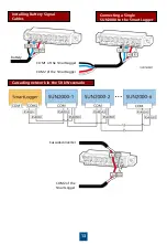
Page 14: ... Battery Signal Cables COM1 of the SmartLogger Battery 13 COM2 of the SmartLogger Connecting a Single SUN2000 to the Smart Logger Cascading network in the 50 kW scenario Cascaded inverter COM2 of the SmartLogger ...

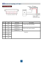
Page 15: ...cription 1 CT1 Primary CT1 U wire on the power grid side 2 CT1 Primary CT1 3 CT2 Primary CT2 W wire on the power grid side 4 CT2 Primary CT2 5 CT3 Reserved 6 CT3 7 CT4 8 CT4 Optional Installing a CT Cable 3 8 Branch Master power distribution panel ...

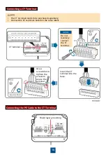
Page 16: ...wdriver to tighten the screws to secure the terminal CT terminal Do not reversely connect the CT terminal Connecting the PE Cable to the CT Terminal The CT terminal needs to be purchased separately Connect the CT terminals based on the cable labels 15 Shield layer grounding ...

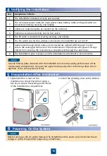
Page 17: ...ompartment and prevent foreign objects from entering the maintenance compartment through the cable holes 8 The installation space is proper and the installation environment is clean and tidy 5 Encapsulation After Installation 1 Tighten the four screws on the maintenance compartment door using a hex key to ensure the sealing performance of the maintenance compartment Use the firestop putty delivere...

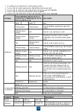
Page 18: ...C environmental alarm For example the input voltage of the PV string is high the PV string is reversely connected or the insulation resistance is low N A Blinking red fast There is an AC environmental alarm such as grid undervoltage grid overvoltage grid overfrequency or grid underfrequency Steady red Steady red Faulty Communicatio ns indicator LED3 N A Blinking green fast Communication is in prog...

Page 19: ...r management system you are advised to use a USB flash drive for upgrade You can insert the USB flash drive with the upgrade package and go to the device upgrade screen to start the upgrade Contact the channel or dealer to obtain the version upgrade package 2 If no USB flash drive is available log in to the SmartLogger WebUI by referring to section 7 4 and choose Maintenance Firmware Upgrade Conta...

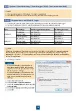
Page 20: ...he IP address of the WAN port is on the 192 168 8 1 192 168 8 255 network segment the IP address of the LAN port is automatically switched to 192 168 3 10 and the default gateway is 192 168 3 1 If the connection port is a LAN port adjust the network configuration of the PC accordingly 3 Set LAN parameters If the SmartLogger is connected to a local area network LAN and a proxy server has been set y...

Page 21: ...hese cases the user is liable for any loss caused to the PV plant If you enter wrong passwords for five consecutive times within 5 minutes your account will be locked out Try again 10 minutes later 1 Enter https XX XX XX XX in the address box of the browser XX XX XX XX is the default IP address of the SmartLogger If you log in to the WebUI for the first time a security risk warning is displayed Cl...

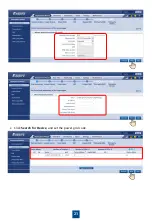
Page 22: ...21 c Click Search for Device and set the power grid code ...

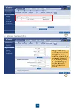
Page 23: ...er meter parameters The parameters are automatically read and do not need to be modified When a CT is connected Backup CT is displayed by default If it is not displayed check whether the cable connection is correct ...

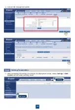
Page 24: ...23 e Connect the management system 1 After completing the settings according to the deployment wizard choose Settings EMS Control and set battery working mode 7 3 3 Setting Parameters ...

Page 25: ...discharge power Power grid charging Enable power grid charging and allow reverse charging for the power grid Maximum grid charging power kW Set the maximum reverse charging power for the power grid Charging cutoff SOC Set the charge cutoff SOC Discharging cutoff SOC Set the discharge cutoff SOC Power grid Charging cutoff SOC Set the power grid charge cutoff SOC 3 Choose Monitoring Running Param Fe...

Page 26: ...ered in backup mode Grid tied Off grid mode switching If this parameter is set to Automatic switching the system switches to the off grid mode when the grid fails and switches to the grid tied mode when the grid recovers Voltage in independent operation Select the voltage in independent operation based on the inverter cable connection 101 V or 202 V Creating a Plant 7 3 4 After the connection mana...

Page 27: ...26 Statement Customer Service Contact Information Area Country R egion Email Phone Japan Japan solarsupportjp huawei com 0120258367 8 Customer Service Contact Information ...

Page 28: ...Huawei Technologies Co Ltd Huawei Industrial Base Bantian Longgang Shenzhen 518129 People s Republic of China solar huawei com ...

Reviews: