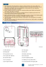
Preparations
3.1
Connect cables in accordance with local installation laws and regulations.
Before connecting cables, ensure that the DC switch on the SUN2000 and all the upstream
and downstream switches connected to the SUN2000 are set to OFF. Otherwise, the high
voltage of the SUN2000 may result in electric shocks.
3
Electrical Connection
The inner diameter of the cable holes is 27 mm. Prepare cables based on site requirements.
Installing PE Cables (Using the Ground Point on the Chassis Enclosure)
3.2
It is recommended that PE cable of the SUN2000 be connected to the nearest ground point.
It is recommended that silica gel or paint be used around the ground terminal after the PE
cable is connected.
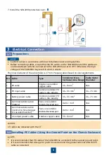
7. Install the SUN2000 protective cover.
5
No. Cable
Type
Conductor Cross-
Sectional Area Range
Cable Outer
Diameter
1
PE cable
Single-core outdoor
copper cable
5.5–8 mm
2
N/A
2
PV input cable
Common outdoor PV
cable in the industry
3.5–5.5 mm
2
5.5–7.3 mm
3
Battery power cable
Common outdoor PV
cable in the industry
3.5–5.5 mm
2
5.5–7.3 mm
4
Communications cable
(battery)
Four-core outdoor
shielded twisted pair
0.20–1 mm
2
N/A
5
Communications cable
(inverter to SmartLogger
or cascaded inverter)
Four-core outdoor
shielded twisted pair
0.20–1 mm
2
N/A
6
AC output power cable
Outdoor copper cable
5.5–8 mm
2
N/A
CT cables are delivered with the CT.


