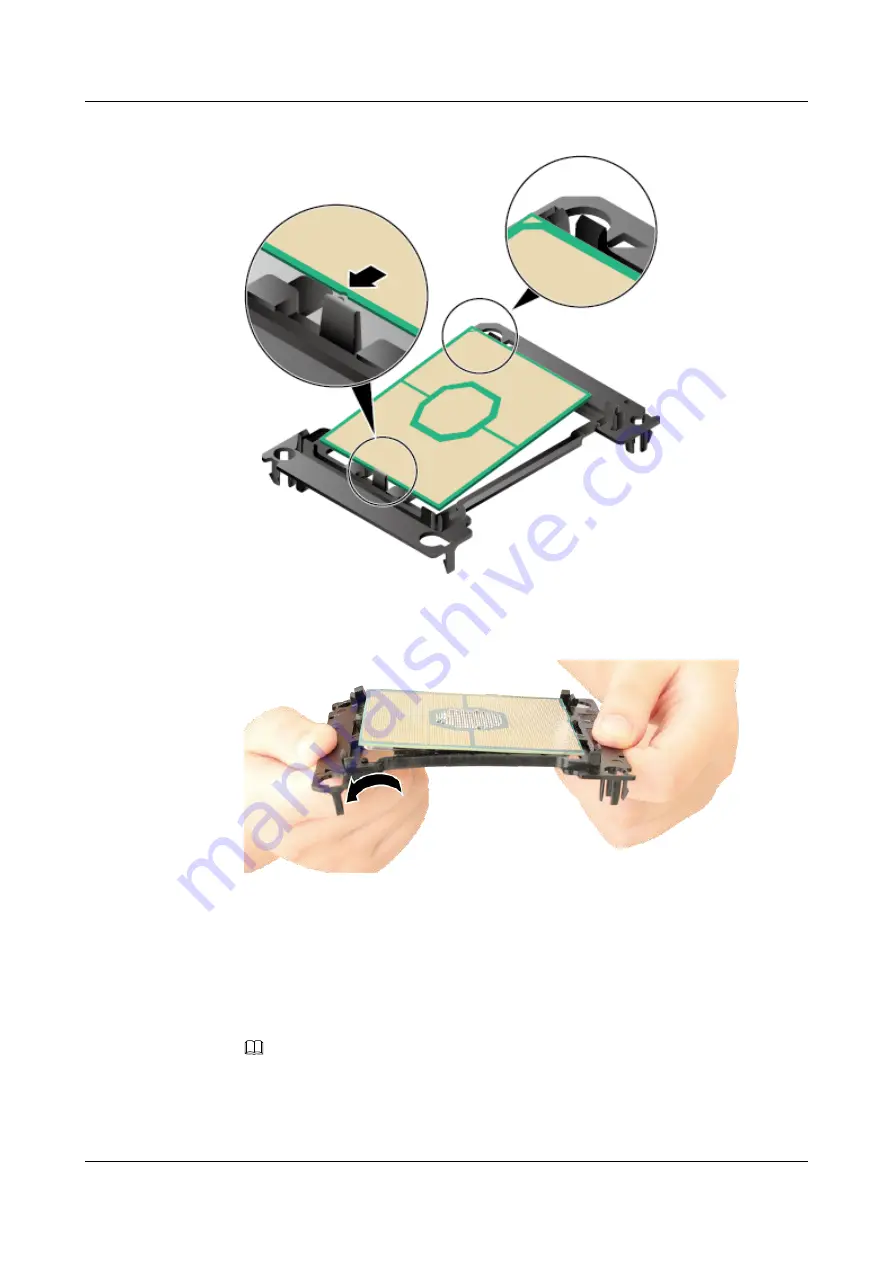
Figure 4-29
Installing one end of the processor
3.
Bend the other edge of the processor carrier in the arrow direction.
Figure 4-30
Installing the other end of the processor
4.
Release the processor carrier so that the other edge of the processor clips into place.
5.
Check that the processor and the carrier are level and the processor is firmly secured. If
the processor is tilted, press the tilted part to fasten it.
Step 11
Apply thermal compound.
1.
Determine the area on the processor that will be in contact with the heat sink, and evenly
apply 0.4 ml of thermal compound on the area.
NOTE
–
When applying thermal compound, place the processor carrier on the desktop.
–
The thermal compound injector has volume marks.
The two-line, five-dot, s-shape, and X-shape patterns are recommended.
FusionServer Pro CH121 V5 Compute Node
Maintenance and Service Guide
4 Parts Replacement
Issue 06 (2019-08-10)
Copyright © Huawei Technologies Co., Ltd.
80


