background image

Information  

Type 

SYS 

Link 

Wireless 

Description 


Startup 

status 

Steady 

green 

NA 

NA 

The device is being started. 

Blinking 

green 

NA 


NA 


The system is working properly. 

Steady 

red 

NA 

NA 

The system fails to load the DRAM or system 
software. 


Running and 

connection 


0.5Hz 


Off 


Off 

The system is working properly. However, the 
Ethernet is not connected. Radios are disabled 
and no user is connected to the AP. 


Blinking 

green 

The system is working properly, but the Ethernet 
is not connected. The AP has wireless users 
connected to the 2.4 GHz band and is 
transmitting data. The indicator blinks more 
quickly when more packets are being transmitted. 


Blinking 

yellow 

The system is working properly, but the Ethernet 
is not connected. The AP has wireless users 
connected to the  5 GHz band and is transmitting 
data. The indicator blinks more quickly when 
more packets are being transmitted. 

Blinking 

green and 

yellow 

alternately 

The system is working properly, but the Ethernet 
is not connected. The AP has wireless users 
connected to the 2.4 GHz and 5 GHz bands and 
is transmitting data. 


0.5Hz 


Steady or  

Blinking  

green 


Off 

The system is working properly, the Ethernet is 
connected, and radios are disabled. The indicator 
blinks more quickly when more data is being 
transmitted. 


Blinking  

green 

The system is working properly, and the Ethernet 
is connected. The AP has wireless users 
connected to the 2.4 GHz band and is 
transmitting data. The indicator blinks more 
quickly when more packets are being transmitted. 


Blinking 

yellow 

The system is working properly, and the Ethernet 
is connected. The AP has wireless users 
connected to the 5 GHz band and is transmitting 
data. The indicator blinks more quickly when 
more packets are being transmitted. 

Blinking 

green and 

yellow 

alternately 

The AP has wireless users connected to the 2.4 
GHz and 5 GHz bands and is transmitting data. 
The indicator blinks more quickly when more 
packets are being transmitted. 

21 

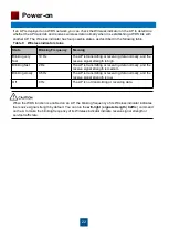
Power-on 

Table 8 Indicator status of the AP6510DN-AGN and AP6610DN-AGN 

Power on the AP and check the indicator status to determine the system running status. 

NOTE

The AP6510DN-AGN supports the PoE function that complies with 802.3at. 


Summary of Contents for AP Series

Page 1: ...AP Series Outdoor Wireless LAN Access Points Quick Start Guide ...

Page 2: ... services and features described in this document may not be within the purchase scope or the usage scope Unless otherwise specified in the contract all statements information and recommendations in this document are provided AS IS without warranties guarantees or representations of any kind either express or implied The information in this document is subject to change without notice Every effort...

Page 3: ...ion engineers Onsite maintenance engineers Network administrators configuring and maintaining the network Symbol Description Indicates a hazard with a high level or medium level of risk which if not avoided could result in death or serious injury Indicates a hazard with a low level of risk which if not avoided could result in minor or moderate injury Indicates a potentially hazardous situation tha...

Page 4: ...For example if you want to obtain AP6610DN AGN documents select AP6610DN AGN 3 NOTE Technical Support If you have trouble in locating or rectifying faults during maintenance or troubleshooting by following instructions in this document contact the Huawei customer service center CSC for help You can also visit http enterprise huawei com click Contact Us in the lower area of the page and select the ...

Page 5: ...latest document issue contains all the changes in previous issues Changes in Issue 02 2013 01 30 This version has the following updates The following information is added FCC compliance and sales regions of AP products Change in Issue 01 2012 10 31 Initial commercial release 4 ...

Page 6: ...ge Different outdoor AP models are sold in different regions depending on whether the APs have passed the FCC certification Table 1 FCC compliance and sales regions of AP products Passed FCC Certification Product Model Sales Region No AP6510DN AGN All regions except Japan and regions that require FCC certification AP6610DN AGN Yes AP6510DN AGN US AP6510DN AGN US Regions that require FCC certificat...

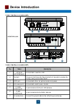
Page 7: ...e dimensions and weights of outdoor APs Table 2 Dimensions and weight Model Dimensions Weight AP6510DN AGN 255mm 255mm 83mm W D H 2 2kg AP6610DN AGN 255mm 255mm 83mm W D H 2 65kg Table 3 Interfaces on outdoor APs AP6510DN AGN 5 5 6 6 1 2 7 ...

Page 8: ...nd restart the AP 3 SFP port Connected to fiber An optical module is required 4 AC power port Connected to an AC power module 5 2 4 GHz antenna port A port connected to the 2 4 GHz antenna 6 5 GHz antenna port A port connected to the 5 GHz antenna 7 Ground screw Connect the ground cable to the AP with a ground screw Table 3 Interfaces on outdoor APs Table 4 Interfaces on outdoor APs 1 2 5 5 6 6 3 ...

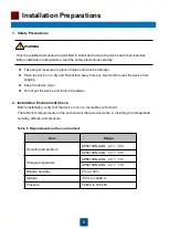
Page 9: ... to install and remove the device and its accessories Before installation and operation read the safety precautions carefully Take proper measures to prevent injuries and device damage Place the device in a dry and flat position away from any liquid and prevent the device from slipping Keep the device clean Do not put the device and tools in the aisles Item Range Operating temperature AP6510DN AGN...

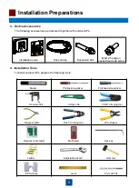
Page 10: ...Ps prepare the following tools Phillips screwdriver Flat head screwdriver Utility knife Wire stripper Network cable tester Multimeter Adjustable wrench Maker RJ45 crimping tool Diagonal pliers Ladder COAX crimping tool Hammer drill Hammer ESD gloves Level 8mm drill bit M4x12 hexagon socket head cap screw Installation suite Hose clamp Expansion bolt Hex key ...

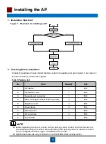
Page 11: ...ling an AP 2 Checking Before Installation Unpack the package Ensure that all the items listed in the packing list are included in the carton If any item is missing contact the supplier Table 6 Packing list NOTE Before unpacking the carton ensure that the packing carton is intact and that the carton is not severely damaged or soaked Stop unpacking if the packing carton is rusted or socked Then inve...

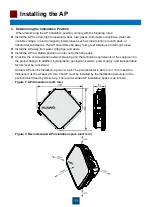
Page 12: ...s and dews Install the AP in a hidden position in order not to disturb people Consider the communication network planning and the technical requirements of the equipment in the project design In addition hydrographic geological seismic power supply and transportation factors must be considered Outdoor APs can be installed on poles or wall The pole diameter is 48 mm to 114 mm and the thickness must...

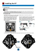
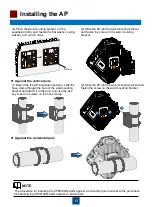
Page 13: ...he wall mounting bracket 2 Use 8 mm drill bit to drill 35 mm to 40 mm deep holes in the drilling positions and install expansion bolts Screw the nut into the expansion tube hammer the expansion bolt into a hole until the flat washer is flattened against the wall and remove the nuts spring washer and flat washer in order 3 Use four M4x12 hexagon socket head cap screws to fasten the wall mounting br...

Page 14: ...her and nuts in order 5 Slide the AP into the wall mounting bracket and fasten the screw on the wall mounting bracket Against the vertical pole 1 Determine the AP installation position slide the hose clamp through the hole of the wall mounting bracket and attach it to the pole and use the hex key to secure screws on the hose clamp 2 Slide the AP into the wall mounting bracket and fasten the screw ...

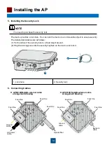
Page 15: ...ity The detailed procedures are as follows 1 Fix the cable of the security lock to a fixed object around 2 Plug the locking piece into the security keyhole on the device and lock it AP6610DN AGN external cable arrangement drawing NOTE 1 2 Feed line Feed line Feed line Feed line Feed line Feed line Feed line Feed line Network cable Ground cable Ground cable AC power cable Optical fiber AP6510DN AGN...

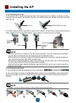
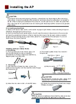
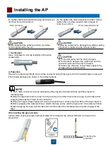
Page 16: ...p and wrap the dustproof cap with insulating tape and waterproof tape Wrap the feed line using one layer PVC black insulation tape three layer waterproof adhesive tape and then three layer PVC black insulation tape Stretch the waterproof adhesive tape evenly and ensure that the upper layer of the tap overlaps 1 2 of the lower layer Each layer should be attached tightly Wrap the three layer waterpr...

Page 17: ... cable is installed properly When removing the AC power cable press the component with the red point You do not need loosen the screw figure 5 Figure 4 Figure 5 Making AC Power Cables Onsite a Preparation 1 The required tools are as follows open end 2 The following table shows the connector wrench 22mmX24mm open end wrench components 22mmX24mm Phillips screwdriver 0 X50mm diagonal pliers and utili...

Page 18: ...e short circuited Connections between the metal shell and the connector jacks can t be short circuited Cable core wires are connected properly to the corresponding connector jacks NOTE Each radio connector must be wrapped by three layers of waterproof tape and three layers of insulating tape Wrap the tape from bottom to top from top to bottom and then from bottom to top Cut the tape after wrapping...

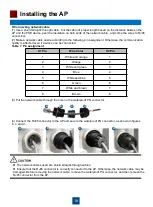
Page 19: ...work cable through the hole on the waterproof PG connector 4 Connect the RJ45 connector to the AP and secure the waterproof PG connector as shown in figures b c and d X1 Pin Wire Color X2 Pin 1 White and orange 1 2 Orange 2 3 White and green 3 4 Blue 4 5 White and blue 5 6 Green 6 7 White and brown 7 8 Brown 8 Table 7 Pin assignment a b c d a b c d The network cables used are shield straight throu...

Page 20: ...n screws and steel wires and then fix the directional outdoor antenna on the pole with an antenna support Lightning rod Flat steel Connect to earth mat Parapet Height of parapet 1200 mm Height of parapet 1200 mm No parapet Antenna support Antenna pole Directional outdoor antenna Lightning rod Flat steel Connect to earth mat Parapet Antenna support Antenna pole Directional outdoor antenna Lightning...

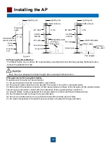
Page 21: ...stall it again after pressing the Reset button Requirements for laying Out Cables Requirements for laying out ground cables 1 All ground cables must be connected to a ground bar 2 The ground cable cannot be led in aerially but buried in the earth or arranged indoor 3 Both ends of the external conductor of the coaxial cable and those of the insulation of the shielded cable should have good electric...

Page 22: ... has wireless users connected to the 2 4 GHz and 5 GHz bands and is transmitting data 0 5Hz Steady or Blinking green Off The system is working properly the Ethernet is connected and radios are disabled The indicator blinks more quickly when more data is being transmitted Blinking green The system is working properly and the Ethernet is connected The AP has wireless users connected to the 2 4 GHz b...

Page 23: ... AP is deployed on a WDS network you can check the Wireless indicator on the AP to determine whether the AP transmits and receives wireless data normally when it is establishing a WDS link with another AP The Wireless indicator has four possible states as described in the following table Table 9 Wireless indicator status When the WDS function is enabled on an AP the blinking frequency of its Wirel...

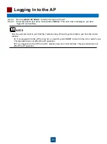
Page 24: ... the AP s default IP address 192 168 0 1 and the subnet mask is 255 255 255 0 After the configuration is complete run the ping 192 168 0 1 command on the PC to check whether the PC can be pinged If the ping operation succeeds the connection is set up successfully If the ping operation fails the connection fails to be set up Check whether the network cable works properly Step 3 Access the command l...

Page 25: ...g In to the AP If you logged in to the AP from an AC or a switch press Ctrl T to return to the AC or switch view This operation does not affect the AP operation If you logged in to the AP from a PC directly close the Telnet window This operation does not affect the AP operation Run the exit command to exit from the Telnet window When the system fails to exit from the Telnet window NOTE ...

Page 26: ...O Cable connector O O O O O O Power adapter O O O O O O Auxiliary equipment O O O O O O O Indicates that the concentration of the hazardous substance contained in all the homogeneous materials of this part is below the limit requirement of the SJ T 11363 2006 standard X Indicates that the Concentration of the hazardous substance contained in all the homogeneous materials of this part is above the ...

Page 27: ...roper handling in transportation and assembly 2 The defects are caused by the fact that the product is dismantled or altered by anyone that is not from a Huawei authorized service partner 3 The defects are caused by the fact that the product is used in a harsh environment that is not suitable for the operation of the product 4 The defects are caused by any force majeure including but not limited t...

Reviews: