background image

Installing Accessories

Hard Disk Drive Cage

Chapter 2

20

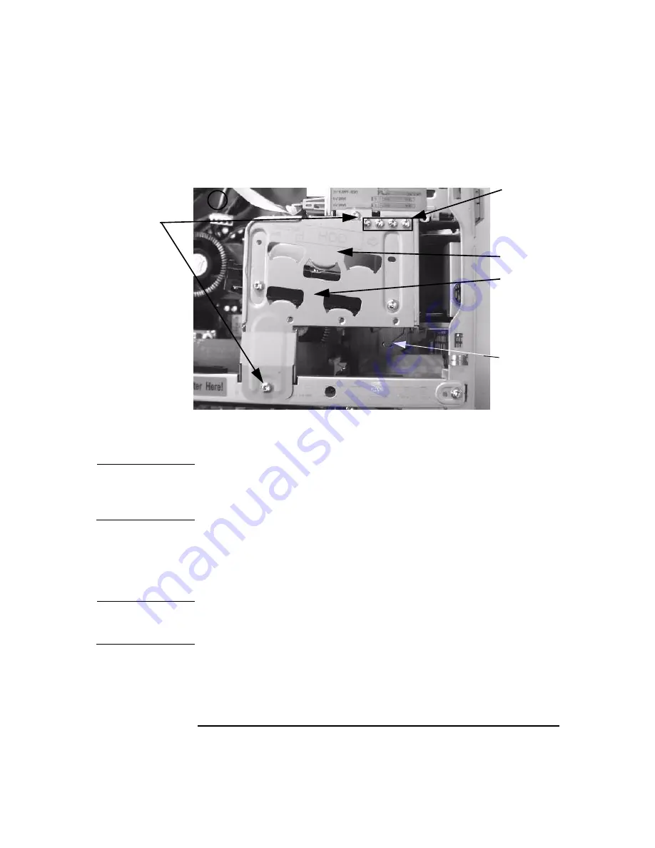
Figure 2-3

Hard Disk Drive Cage

Closing and Securing the Hard Disk Drive Cage

CAUTION

Clear all cables from the area where the hard disk drive cage rests on the
chassis beam assembly. If cables are in the way, you may damage them
when you move the hard disk drive cage back into the closed position.

To close and secure the hard disk drive cage:

1. Push in the clip shown in Figure 2-3 on page 20 and rotate the hard

drive cage carefully into the closed position.

CAUTION

Do not allow the cage to drop into place. This could damage the hard
drive(s).

2. Fasten the cage with two screws in the locations shown in Figure 2-3

on page 20.

Step 2

Upper Bay

Lower Bay

Hard Disk
Drive Cage
Clip

Screws for
installing a
second
hard disk
drive

This manual downloaded from http://www.manualowl.com

Summary of Contents for Workstation x4000

Page 1: ...hp x4000 workstation accessory installation guide This manual downloaded from http www manualowl com ...

Page 2: ...This manual downloaded from http www manualowl com ...

Page 3: ...Accessory Installation Guide HP x4000 Workstation Manufacturing Part Number A6068 90010 Edition E0501 Copyright 2001 Hewlett Packard Company This manual downloaded from http www manualowl com ...

Page 4: ...emarks or trademarks of NVIDIA Corporation Matrox is a registered trademark of Matrox Electronic Systems Ltd Microsoft Windows MS DOS and Windows NT are registered trademarks of the Microsoft Corporation Pentium and AGPset are trademarks of Intel Corporation WOL Wake on LAN is a trademark of IBM Rambus and RDRAM are registered trademarks of Rambus Inc Direct Rambus Direct RDRAM and RIMM are tradem...

Page 5: ...e 19 Opening the Hard Disk Drive Cage 19 Closing and Securing the Hard Disk Drive Cage 20 Chassis Beam Assembly 22 Removing the Chassis Beam Assembly 22 Installing the Chassis Beam Assembly 23 Memory Expander Card MEC 25 Removing the MEC 25 Installing the MEC 26 System Memory 27 Upgrading Memory 27 Installing Memory 29 Graphics Card 32 Removing a Graphics Card 32 Installing a Graphics Card 33 SCSI...

Page 6: ... or DVD 41 Determining IDE Connections 42 Removing a CD ROM CD RW or DVD 42 Installing a CD RW or DVD 43 Load the Software Applications for Your CD RW 44 Processor 45 Removing a Processor 45 Installing a Processor 47 Updating Your Operating System 49 This manual downloaded from http www manualowl com ...

Page 7: ...pt to make any adjustment to the laser unit Refer to the label on the CD ROM for power requirements and wavelength This product is a class I laser product WARNING For your safety never remove the Workstation cover without first disconnecting the power cord from the power outlet and removing any connection to a telecommunications network If a Power Protection Device is fitted to your Workstation yo...

Page 8: ...nals unless the telephone line has been disconnected at the network interface Use caution when installing or modifying telephone lines Avoid using a telephone other than a cordless type during an lightning storm There may be a risk from lightning Do not use the telephone to report a gas leak in the vicinity of the leak Never touch or remove the communications board without first removing the conne...

Page 9: ...ons and the latest versions of drivers utilities BIOS and firmware The web accessible documentation includes the x4000 Technical Reference Troubleshooting Guide This guide contains detailed information about your Workstation including the system board switches power consumption and acoustic noise emission test configurations troubleshooting and system architecture Additional Web Sites www hp com w...

Page 10: ...6 This manual downloaded from http www manualowl com ...

Page 11: ... Understanding the Workstation Hardware This chapter gives you a brief overview of your Workstation s internal components system board and Memory Expander Card MEC This manual downloaded from http www manualowl com ...

Page 12: ...n Figure 1 1 Figure 1 1 HP x4000 Workstation Power Supply Unit Main Fan Spare Mounting Rails Two 3 5 inch shelves Three 5 25 inch drive shelves can be used for removable drives Hard Disk Drive Cage holds up to 2 SCSI hard drives Chassis Beam Assembly this holds the Memory Expander Card in place This manual downloaded from http www manualowl com ...

Page 13: ...fferent Figure 1 2 HP x4000 Workstation System Board Secondary IDE Controller Floppy Disk Drive Controller Up to six accessory cards can be installed Two 64 bit PCI slots Three 32 bit PCI slots One AGP PRO 4X slot graphics Primary IDE Controller MEC Connector CPU 0 Socket CPU 1 Socket Internal SCSI External SCSI This manual downloaded from http www manualowl com ...

Page 14: ...on is not located on the system board Instead a Memory Expander Card MEC plugs into the system board and contains up to eight memory modules in connectors 1A J5 through 4B J4 The MEC is shown in Figure 1 3 Figure 1 3 x4000 Memory Expander Card 1B J1 2B J2 3B J3 4B J4 3A J7 4A J8 1A J5 2A J6 This manual downloaded from http www manualowl com ...

Page 15: ...Chapter 2 13 2 Installing Accessories This manual downloaded from http www manualowl com ...

Page 16: ...Memory on page 27 Graphics Card on page 32 SCSI Hard Drive on page 37 CD RW or DVD on page 41 Processor on page 45 NOTE Check your configuration every time you install remove or upgrade an accessory For instructions on how to check your configuration using the HP Setup program refer to the Getting Started Guide that came with your x4000 Workstation or the HP x4000 Workstation Technical Reference G...

Page 17: ...ower Protection Device cables before any servicing operation Always replace the cover before switching the Workstation on again To remove the cover Figure 2 1 1 Turn off the display and shut down the Workstation Disconnect all power cables and any LAN or telecommunications cables 2 If necessary unlock the cover on the back of the Workstation 3 Unscrew the two thumb screws located at the back of th...

Page 18: ...Installing Accessories Cover and Front Bezel Chapter 2 16 Figure 2 1 Removing the Cover 2 3 4 This manual downloaded from http www manualowl com ...

Page 19: ...are adding or removing devices in the 5 25 inch or 3 5 inch front drive bays To remove the bezel 1 Gently lift the four plastic tabs starting with the bottom tab and working your way to the top 2 Rotate the bezel off the Workstation chassis Figure 2 2 Removing the bezel Plastic Tabs This manual downloaded from http www manualowl com ...

Page 20: ...fy that the plastic tabs on the left side of the bezel click into position on the Workstation chassis The bezel should be flush against the Workstation 3 Standing at the back of the Workstation lower the cover onto the chassis aligning the guide rail on the bottom inside edge of the cover with the bottom edge of the Workstation chassis 4 Shut the cover ensuring that the guides on the top of the co...

Page 21: ...drive s CAUTION Do not rotate the cage before you disconnect the cables 2 Remove and retain the two Torx screws that hold the cage closed as shown in Figure 2 3 3 Pull the cage toward you until you hear the hard disk drive cage clip catch the cage WARNING Make sure the clip has latched the cage in the open position An injury could result if the cage falls This manual downloaded from http www manua...

Page 22: ...ive cage back into the closed position To close and secure the hard disk drive cage 1 Push in the clip shown in Figure 2 3 on page 20 and rotate the hard drive cage carefully into the closed position CAUTION Do not allow the cage to drop into place This could damage the hard drive s 2 Fasten the cage with two screws in the locations shown in Figure 2 3 on page 20 Step 2 Upper Bay Lower Bay Hard Di...

Page 23: ...nnector farthest from the system board to the hard drive in the upper bay b Attach the remaining SCSI connector to the hard drive in the lower bay 5 Connect the power supply cable s to the hard disk drive s a Connect the power supply cable labeled P3 to the hard disk drive in the upper bay b Attach the power supply cable labeled P4 to the hard disk drive in the lower bay SCSI cable connected to in...

Page 24: ...move the chassis beam assembly Removing the Chassis Beam Assembly To remove the chassis beam assembly 1 Open the hard disk drive cage see page 19 2 Remove the screw that holds the chassis beam assembly in place 3 Carefully rotate the chassis beam assembly off the chassis Figure 2 5 Chassis Beam Assembly Step 2 This manual downloaded from http www manualowl com ...

Page 25: ...and the graphics card making sure the MEC and graphics card retainer clips are centered on the cards as shown in Figure 2 6 and Figure 2 7 CAUTION Make sure the retaining clips slide easily over the cards or the clips may put undue pressure on the card connectors 2 Replace the screw that holds the chassis beam assembly in place Figure 2 6 MEC Retainer Clip Retaining clip on MEC This manual downloa...

Page 26: ...ics card by engaging the Universal Retainer piece see Figure 2 7 NOTE Not all systems use the chassis beam assembly Universal Retainer piece to hold the graphics card in place Your system may use a separate graphics card retainer beam see Figure 2 14 Figure 2 7 Secure the Universal Retainer Piece Graphics Card This manual downloaded from http www manualowl com ...

Page 27: ...stallation place the Workstation on its side with the system board facing upwards 4 Rotate the hard disk drive cage to the open position see page 19 5 Remove the chassis beam assembly see page 22 6 Remove retaining screw that holds the MEC in place and gently remove the MEC from the chassis as shown in Figure 2 8 CAUTION You must remove the MEC to install RIMMs The MEC card guides are not strong e...

Page 28: ...the MEC making sure it is fully seated and tighten the retaining screw 2 Replace the chassis beam assembly see page 23 3 Close and secure the hard disk drive cage see page 20 4 Replace the Workstation cover see page 18 5 Reconnect all power cables and any LAN or telecommunications cables This manual downloaded from http www manualowl com ...

Page 29: ... J3 4B J4 3A J7 and 4A J8 This allows for a total of 8 RIMMs You must adhere to the following rules when loading memory RIMMs must be loaded in matched pairs Matching RIMMs have the same RDRAM size speed and Mbit technology Each RDRAM bank channel must be either completely empty or completely filled as shown in Figure 2 10 Therefore if only one pair of RIMMs is installed in a bank then the remaini...

Page 30: ...2A J6 Memory Bank I consists of RIMM pair 1 1A J5 and 1B J1 RIMM pair 2 2A J6 and 2B J2 Memory Bank II consists of RIMM pair 3 3A J7 and 3B J3 RIMM pair 4 4A J8 and 4B J4 If a memory bank only contains 1 pair of RIMMs the remaining 2 connectors must contain CRIMMs to ensure continuity This manual downloaded from http www manualowl com ...

Page 31: ... Workstation s cover see page 15 4 To ease installation place the Workstation on its side with the system board facing upwards P1 edge P1 edge P1 edge P1 edge 1 Pair of RIMMs 2 Pairs of RIMMs 3 Pairs of RIMMs 4 Pairs of RIMMs CRIMM CRIMM RIMM 1A RIMM 1B RIMM 1A RIMM 1A RIMM 1A RIMM 1B RIMM 1B RIMM 1B RIMM 2A RIMM 2B RIMM 2A RIMM 2A RIMM 2B RIMM 2B CRIMM RIMM 3A CRIMM RIMM 3B RIMM 3A RIMM 4B RIMM 4...

Page 32: ...pushing down on them and remove the CRIMM from the socket See Figure 2 11 on page 31 b If you are replacing existing RIMMs open the retaining clips by pushing down on them and remove the existing RIMMs from their sockets NOTE Always store any removed RIMMs and CRIMMs in a safe place for future use CRIMMs may be stored in an empty memory bank if one is available c Install your new RIMMs or CRIMMs e...

Page 33: ...ee page 20 12 Replace the Workstation cover see page 18 13 Reconnect all power cables and any LAN or telecommunications cables 14 Start the Workstation and check the Summary Screen by pressing Esc when prompted to verify the new configuration The Summary Screen displays the amount of memory MEC Voltage Regulator Module not on all MECs Retaining Clip fully engaged This manual downloaded from http w...

Page 34: ...with the system board facing upwards 5 Rotate the hard disk drive cage to the open position see page 19 6 Remove the chassis beam assembly see page 22 7 Before removing the graphics card If your graphics card came with a separate graphics retainer beam as shown in Figure 2 14 on page 34 a Remove the screw that attaches the graphics card and the graphics retainer beam to the rear slot panel b Remov...

Page 35: ...ing card remove the current card see page 32 2 Unscrew and remove the rear slot panel that corresponds AGP PRO 4X connector The screw you removed is used to retain the graphics card NOTE If you are installing a full length graphics card you must remove the graphics board retaining screw near the front of the chassis as shown in Figure 2 13 This manual downloaded from http www manualowl com ...

Page 36: ...iner pieces from the chassis beam assembly shown in Figure 2 15 and store these in a safe place for future use b Using the screw that you removed from the rear slot panel and the graphics card retaining screw shown in Figure 2 13 attach the graphics retainer beam as shown in Figure 2 14 Figure 2 14 Graphics Card Retainer Beam Full Length Graphics Card Retaining Screw This screw attaches the retain...

Page 37: ...s cards Remove the retainer clip you don t need c Move the remaining retainer clip to the center position shown in Figure 2 15 If your graphics card is too shallow for the clip to hold it tightly in this position return it to the other arm Figure 2 15 Retainer Pieces on the Chassis Beam Assembly 5 Replace the chassis beam assembly see page 23 If your graphics card has a retainer beam once the chas...

Page 38: ...d Chassis Beam Assembly 6 Close and secure the hard disk drive cage see page 20 7 Replace the Workstation cover see page 18 8 Reconnect all power cables and any LAN or telecommunications cables Chassis Beam Assembly Graphics Card Retainer Beam This manual downloaded from http www manualowl com ...

Page 39: ...drive Your Workstation has on board SCSI capability You can connect up to two internal SCSI hard disk drives Figure 2 17 shows the internal and external SCSI connectors on the system board Figure 2 17 SCSI System Board Connectors Internal SCSI connector External SCSI connector This manual downloaded from http www manualowl com ...

Page 40: ...les 2 Remove the Workstation s cover see page 15 3 Open the hard disk drive cage see page 19 4 Remove the hard disk drive from the cage by removing the four Torx screws that hold the drive in place as shown in Figure 2 18 Figure 2 18 Removing the Hard Disk Drive These 4 screws 2 front 2 back hold one hard drive in place Upper Bay Lower Bay Screws for installing a second hard disk drive This manual...

Page 41: ... should assign an unused SCSI ID to the second SCSI hard disk drive SCSI ID 1 is recommended The SCSI ID is configured with jumpers on the SCSI hard disk drive Refer to the information label on the hard disk drive or the HP x4000 Technical Reference Guide at www hp com workstations support for additional details on setting the SCSI ID Table 2 1 SCSI ID Settings SCSI ID Used By 0 First SCSI hard dr...

Page 42: ...Install the hard disk drive s in the cage using the screws provided on the hard disk drive cage as shown in Figure 2 18 on page 38 a If you only have one hard drive install it in the bottom bay b If required install a second hard drive in the top bay c Align the screw holes on each hard drive with the openings in the hard disk drive cage d Fasten each hard disk drive to the cage with four screws t...

Page 43: ...DE system board connectors are shown in Figure 1 2 on page 11 An IDE cable is shown in Figure 2 19 Figure 2 19 IDE Data Cable Connects to system board IDE controller Connects to Master IDE device Connects to Slave IDE device Red stripe indicates Pin 1 This manual downloaded from http www manualowl com ...

Page 44: ...y and shut down the Workstation Disconnect all power cables and any LAN or telecommunications cables 2 Remove the Workstation s cover and front bezel see page 15 for instructions 3 Disconnect the power data and audio cables from the old drive 4 Remove the drive by pressing the two front rail clips inward and sliding the drive out the front of the chassis 5 Remove the guide rails by gently prying t...

Page 45: ... the sticker on the Workstation chassis for the correct rails for your drive Insert the guide rails in the two holes located at the bottom of the drive The guide rails are not side specific 5 Align the guide rails on both sides of the drive with the internal shelf guides then slide the drive until it clicks into position You should put your Master device in the top bay and your Slave device in the...

Page 46: ...tallation begins automatically 2 When the installation window appears a dialog box appears asking you to select your language Select the language you wish to install 3 Select one of these choices and follow the on screen directions for installation Easy CD Creator Direct CD 4 When the installation wizard returns you must restart your system before installation is complete To restart your system a ...

Page 47: ...es it easier to detach the heatsink Be very careful when removing the heatsink If your processor turbo cooler fan is not operating the heatsink may be very hot Under normal circumstances the turbo cooler fan is operational and a slight twist of the heatsink should release it from the processor To remove a processor 1 Turn off the display and shut down the Workstation Disconnect all power cables an...

Page 48: ... heat transfer 10 Open the Zero Insertion Force ZIF lever located at the side of the processor socket until it is in the vertical position depending on the socket design the handle may need to go past vertical then carefully lift out the processor To avoid bending the processor pins keep the processor perfectly flat when removing it 11 Store the processor in an anti static bag such as the one prov...

Page 49: ...r to the notches on the ZIF socket Then carefully lower the new processor into place When the processor is fully inserted close the ZIF lever CAUTION Be extremely careful when you insert the processor If you bend one of the pins it will not go into the socket Figure 2 22 Inserting a Processor 8 Affix the new thermal interface material provided with the new processor to the top of the processor 9 A...

Page 50: ...d CPU1 on the system board 11 Replace the MEC card 12 Replace the Chassis Beam Assembly see page 23 13 Close and secure the hard disk drive cage see page 20 14 Replace the Workstation s cover see page 18 15 Reconnect all the power and telecommunications cables 16 Update your operating system see page 49 This manual downloaded from http www manualowl com ...

Page 51: ...hange the type of support double click on this icon to bring up the ACPI PC properties 5 In the Driver tab select Update Driver The Upgrade Device Driver Wizard appears and you must select Next to continue 6 Choose to display a list of all the known drivers and click Next 7 When all the drivers are located click the radio button to show all hardware of this device class select one of the following...

Page 52: ...Installing Accessories Processor Chapter 2 50 This manual downloaded from http www manualowl com ...

Page 53: ...This manual downloaded from http www manualowl com ...

Page 54: ...Part Number A6068 90010 Printed in U S A E0501 This manual downloaded from http www manualowl com ...

Reviews: