Chapter 6
Installing Additional Boards
48
Installing Accessory Boards
Use this procedure to install accessory boards and observe the installation
guidelines listed earlier.
1. If the Server is already installed and working, power down the Server.
Refer to Chapter 2, "Controls, Ports, and Indicators."
2. Disconnect the power cables and any external cables connected to the Server.
If necessary, label each one to expedite re-assembly.
3. Remove the side cover and lay it aside.
Refer to Chapter 3, "Opening and Closing the HP Server."
WARNING
The power supply will continue to provide standby current to
the Server until the power cable is disconnected.
CAUTION
Wear a wrist-strap and use a static-dissipating work surface
connected to the chassis when handling components. Ensure
the metal of the wrist-strap contacts your skin.
4. Lay the Server on its side (components showing) for the best access to the
accessory board slots.
5. Read the documentation included with the accessory board and follow any
special instructions.
NOTE
Adding a PCI-to-PCI bridge board to the HP Server may alter
the Server's boot order. This boot order can be changed using
the Setup Utility (press [
F2
] during the boot process). Refer to
"Boot Priority" earlier in this chapter.
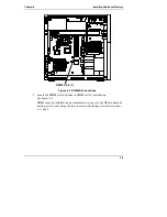
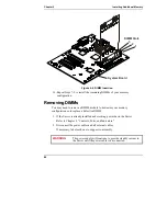
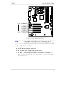
6. Identify the accessory slot number to be used. See Figure 6-1.
The SCSI model should already have the SCSI controller board installed in
PCI slot P1.
NOTE
Refer also to "System Board Layout" in the Appendix A,
"Specifications" for connections not shown in Figure 6-1.

